Chapters
Table of Contents
Troubleshooting

Subscribe to Our Youtube Channel
Related Manuals for RUTHMAN Gusher Pumps 7071 Series


Summary of Contents for RUTHMAN Gusher Pumps 7071 Series
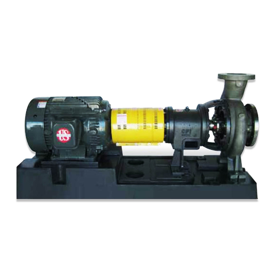
- Page 1 GUSHER PUMPS, INC. 115 INDUSTRIAL DRIVE WILLIAMSTOWN, KY 41097 PHONE: 859-824-3100 FAX: 859-824-7428 www.gusher.com 7071 SERIES ANSI STANDARD DIMENSION AND VORTEX PROCESS INDUSTRY PUMPS MAINTENANCE • INSTALLATION • OPERATIONS...
- Page 2 PUMP SAFETY TIPS OPERATION SAFETY APPAREL • Do not operate below minimum rated flow, or with • Insulated work gloves when handling hot bearings or suction/discharge valves closed using bearing heater • Heavy work gloves when handling parts that have sharp •...
-
Page 3: Table Of Contents
TABLE OF CONTENTS GENERAL INFORMATION ...................4 INSTALLATION ......................7 OPERATION ......................14 MAINTENANCE ......................17 DISASSEMBLY ......................22 REASSEMBLY ......................26 APPENDIX .........................32... -
Page 4: General Information
GENERAL INFORMATION PRECAUTIONS ............................5 PUMP DESCRIPTION ..........................5 NAMEPLATE INFORMATION .......................6 RECEIVING and INSPECTION ......................7 STORAGE ............................7 HANDLING ............................7 PRECAUTIONS ! WARNING ! • NEVER operate pump below recommended Personal injury will result if proce- minimum flow or when dry. dures outlined in this manual are not •... - Page 5 Heavy Duty Casings - 300 psi wall thickness External Impeller Adjustment - Like new clear- increases life under corrosive and erosive con- ance can be maintained with simple external ditions. All sizes are self-venting with centerline adjustment in just minutes to maintain original discharge.
- Page 6 RECEIVING and INSPECTION 4. Pump suction and discharge ports must be Gusher Pumps, Inc. has taken great care in covered to prevent foreign material from preparing your pump for shipment, however, getting into the pump and causing damage due to circumstances beyond our control, your when pump is started at a later date.
-
Page 7: Installation
INSTALLATION PREPARATION ............................8 LOCAL/FOUNDATION .........................8 LEVEL BASEPLATE ........................9-10 COUPLING ALIGNMENT PROCEDURE ...................10 ALIGNMENT CHECKS .........................10 ALIGNMENT CRITERIA ........................11 ANGULAR ALIGNMENT.......................11 PARALLEL ALIGNMENT ......................11 ALIGNMENT TROUBLESHOOTING ....................11 GROUT BASEPLATE .........................12 PIPING ...............................12 SUCTION PIPING ........................13 DISCHARGE PIPING ........................14 FINAL PIPING CHECK .........................14 PREPARATION If your pump has just been taken out of stor- When preparing your pump for installation,... -
Page 8: Level Baseplate
reduce vibration and must be rigid enough to space of approximately 2” should be left be- resist the torque it may be subjected to. The tween the foundation and the bottom of the foundation should be 2” to 6” larger than the base for grouting. -
Page 9: Coupling Alignment Procedure
1. Coat all jack screws with an anti-seizing 6. Turn down the center jack screws until they compound to allow for easy removal after are resting on their metal plates. the grout has cured. 7. Move the two levels to the pump pads. 2. -
Page 10: Alignment Criteria
Alignment Criteria Angular Alignment Good alignment is achieved when the differenc- Check angular alignment with a micrometer or es between the readings is .010 or less when caliper. Measure from the outside of one flange the pump is at operating temperature. How- to the outside of the other flange at intervals ever, during the installation phase it is neces- around the periphery of the coupling, DO NOT... -
Page 11: Grout Baseplate
GROUT BASEPLATE 1. Clean the areas on the baseplate that will 3. Pour grout into form being sure that it flows contact grout. Do not use oil-based clean- under the base. Fill to within 3/4” to 1” from ers because the grout will not bond to it. the bottom of the base. -
Page 12: Suction Piping
2. Before connecting the piping to the pump, 4. When using a strainer on the suction, install ensure that grout has hardened and the it as close to the pump as possible and se- foundation bolts have been tightened. lect a strainer with a net area of at least four times that of the suction pipe. -
Page 13: Discharge Piping
4. Whenever possible avoid dynamic suction is required to prevent pump or seal damage lifts of more than 15’. from reverse flow through the pump when the motor is turned off. 5. A means of priming the pump must be pro- vided. -
Page 14: Operation
OPERATION PREPARATION FOR START-UP ......................15 CHECK ROTATION ........................15 CHECK IMPELLER CLEARANCE ....................15 COUPLE PUMP AND MOTOR ...................... 16 PRIME PUMP ..........................16 INITIAL STARTING ..........................17 OPERATION ............................17 FINAL ALIGNMENT ..........................17 PREPARATION FOR START-UP Check Rotation 1. - Page 15 Couple Pump and Motor to fill the discharge pipe several feet above the pump discharge. 1. Lock out power to motor to prevent acci- dental rotation and physical injury. 3. After filling pipe and pump close air vent. 2. Install and lubricate coupling per manufac- 4.
- Page 16 INITIAL STARTING 1. The gate valve in the discharge line should 3. If your pump is packed, loosen packing be closed and gradually opened as the gland screws to allow free leakage. Then motor reaches full speed (approximately 5 tighten screws uniformly on packing gland to 10 seconds).
-
Page 17: Maintenance
MAINTENANCE BEARINGS ............................18 OIL LUBRICATED........................18 GREASE LUBRICATED ....................... 18 COUPLING ALIGNMENT ........................19 SHAFT SEALS ............................ 19 PACKED PUMPS ........................19 MECHANICAL SEALS ......................... 20 SETTING IMPELLER CLEARANCE ....................21 TROUBLESHOOTING ........................22 BEARINGS All pumps are lubricated at the Gusher plant Grease Lubricated and should not require additional lubrication for approximately 1200 hours of operation. -
Page 18: Coupling Alignment
COUPLING ALIGNMENT tion. Again, we strongly recommend setting up Coupling alignment must be checked before and following a routine maintenance program and after initial startup, after 300 hours of oper- to ensure optimum life from your pump. ation, and again after 1200 hours of operation. Follow procedures given in the Installation sec- SHAFT SEALS Packed Pumps... -
Page 19: Mechanical Seals
yarn packings which should be snugged up very gently. Then wrench in gradually.. .af- ter the pump is back in operation.) Joints of successive rings should be staggered and kept at least 90 apart. Each individual ring should be firmly seated with a tamping tool. When enough rings have been individually seated so the nose of the gland will reach them, individual tamping should be supple-... -
Page 20: Setting Impeller Clearance
SETTING IMPELLER CLEARANCE ! WARNING ! Lock out motor power to prevent acciden- tal startup and physical injury. Over time a change in pump performance may be noticed. Performance can usually be re- newed by resetting the impeller clearance. Using a dial indicator (Fig. 10): 1. -
Page 21: Troubleshooting
TROUBLESHOOTING No liquid delivered Vibration • Pump not primed • Bent shaft • Speed too low* • Pipe strain • Discharge head too high • Impeller clogged • Suction line or suction strainer is • Coupling alignment off clogged • Impeller completely clogged Not enough pressure •... -
Page 22: Disassembly
DISASSEMBLY TOOLS REQUIRED ..........................23 DISASSEMBLY ...........................23 INSPECTION ............................25 TOOLS REQUIRED • Spanner Wrench • Brass Drift Punch • Shaft wrench • Lifting sling • 9/16”, 3/4”, 7/8”, 15/16” Open End Wrench- • Feeler Gauge • Dial Indicator • 7/16” Open End Wrench (L Frame) •... - Page 23 2. Drain piping and impeller housing. 10. Mark location of coupling hub on the shaft, then remove. 3. Remove coupling guards (see Appendix 3) and coupling sleeve. 11. Remove impeller (25) from the rotating as- sembly. To remove impeller, place shaft 4.
- Page 24 15. On packed pumps, remove packing and 21. On L power frames remove radial bearing shaft sleeve (16) from either stem plate (23) retainer (13b) from bearing frame (13). Re- or shaft (9). move oil seal (15) from radial bearing re- tainer.
- Page 25 4. Inspect the shaft (9) and sleeve (16) for 6. Inspect stem plate (23) for pitting or wear grooves or pitting, replace if any are found. greater than 1/8” deep, and make sure that Ensure the shaft bearing fits are within the the gasket surface is clean.
-
Page 26: Reassembly
REASSEMBLY REASSEMBLY ........................... 27 MECHANICAL SEAL ........................31 PACKING ............................. 31 ASSEMBLY TROUBLESHOOTING ....................32 TABLE 6 7071 SERIES BOLT TORQUE LOCATION LUBRICATED THREADS DRY THREADS 6” 7071S 30 FT-LBS 45 FT-LBS IMPELLER HOUSING 8” 7071S 20 FT-LBS 30 FT-LBS BOLTS 7071M 30 FT-LBS... - Page 27 3. Thread locknut (4) onto shaft and tighten until snug. On M power frame use snap ring (4). 4. Coat outside of thrust bearing (5) and the inside of bearing housing (6) with oil. Install bearing housing onto shaft/bearing assem- bly.
- Page 28 12. Attach pedestal (14) to bearing frame, hand tighten bolts. 13. On L power frame, install end plate gas- ket (13a), and end plate (13) on the bearing frame. All Models 1. Support the power frame in a horizontal po- sition.
- Page 29 work surface or a solid block. Repeat pro- cess a few times to tighten impeller. (Fig. Install oil seal (15) in bearing frame. Install stem plate (23) to stem (18). Check stem plate Rotate shaft one turn, if 14. Loosen locking and jacking screws in bear- reading varies more than .005 in.
- Page 30 Mechanical Seals 1. Blue the shaft sleeve (16). Scribe a mark at the face of stem plate to use as reference for installation of mechanical seal. (Fig. 24) Packed Pumps 1. Install packing and gland according to pro- cedures in the Maintenance section of this manual.
- Page 31 6. Check total travel of impeller in the casing, if it is more than .030 in. improper parts or installation or too much pipe strain is pres- ent. Determine cause and correct before proceeding. 7. Adjust impeller clearance using procedures in the Maintenance section of this manual.
-
Page 32: Appendix
APPENDIX APPENDIX 1 - SPARE PARTS ......................33 APPENDIX 2 - DRAWINGS......................35- 37 APPENDIX 3 - COUPLING GUARD INSTALLATION ................38 APPENDIX 4 - BEARING INSTALLATION ...................39 APPENDIX 7 - RECOMMENDED MINIMUM FLOW ................40 APPENDIX 1 - SPARE PARTS If a spare pump cannot be justified, Gusher recommends several parts be kept in your stock for emergency situations. - Page 33 APPENDIX 2 - DRAWINGS...
- Page 36 APPENDIX 3 - COUPLING GUARD INSTALLATION 3. After coupling guard half has been posi- ! WARNING ! tioned around the end plate, secure it with Before working with coupling guards, the a bolt, nut, and two washers through the motor must be de-energized, the motor round hole in the front of the guard half.
- Page 37 APPENDIX 4 - BEARING INSTALLATION inside and out, and the inside diameter of 1. Begin by cleaning your work area, contami- the tubing should be slightly greater than the nants can cause bearing failures as fast as bearing bore. The ends of the tubing should any other reason.
- Page 38 APPENDIX 7 – RECOMMENDED MINIMUM FLOW 7071 SERIES RECOMMENDED MINMUM FLOW (GPM & MAXIMUM DIAMETER) Pump Models 2 Pole 60 Hz 2 Pole 50 Hz 4 Pole 60 Hz 4 Pole 50 Hz 6 Pole 60 Hz 6 Pole 50 Hz 6 Pole 60 Hz 3450 RPM 2850 RPM 1750 RPM...
- Page 39 Pumps, and the coining of the term “coolant pump”. Fax: 859-824-3011 Web: www.gusher.com Wanting to carry on the tradition of quality and reli- ability started by his father, Thomas R. Ruthman Gusher Pumps of Williamstown joined the company in 1949. In the early 1990’s 115 Industrial Drive Williamstown, KY 41097 Thomas R.
Need help?
Do you have a question about the Gusher Pumps 7071 Series and is the answer not in the manual?
Questions and answers