
Subscribe to Our Youtube Channel
Related Manuals for PPI UPI-5D


Summary of Contents for PPI UPI-5D
- Page 1 UPI-5D UPI-5D User Manual Universal Process Indicator with Enhanced Features User Manual...
-
Page 2: Table Of Contents
UPI-5D User Manual CONTENTS FRONT PANEL LAYOUT BASIC OPERATION SET-UP MODE ACCESS AND OPERATION ALARM PARAMETERS RETRANSMISSION PARAMETERS INPUT CONFIGURATION SUPERVISORY PARAMETERS USER LINEARISATION PARAMETERS MECHANICAL INSTALLATION 10. ELECTRICAL CONNECTIONS APPENDIX-A : DC LINEAR SIGNAL INTERFACE... -
Page 3: Front Panel Layout
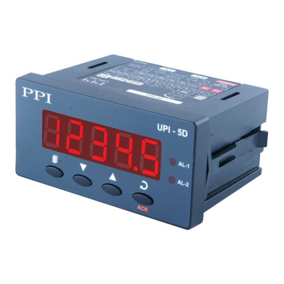
UPI-5D User Manual Section 1 FRONT PANEL LAYOUT The indicator front panel comprises of digital readouts, LED indicators and membrane keys as shown in Figure 1.1(a) for New Version & 1.1(b) for Old Version below. Figure 1.1(a) : New Version... - Page 4 UPI-5D User Manual KEYS There are four tactile keys provided on the front panel for configuring the indicator, setting-up the parameter values. Refer Table 1.2 below. Table 1.2 Symbol Function Press to enter / exit Set-up mode. PAGE Press to decrease the parameter value. Pressing once decreases the value by one count;...
-
Page 5: Basic Operation
UPI-5D User Manual Section 2 BASIC OPERATION POWER UP Upon switching on the power to the indicator, all displays are lit on for approximately 3 seconds. This is followed by the indication of the model name and Version Number for 1 second each. - Page 6 UPI-5D User Manual The operator parameters are described in Table 2.2. Note that the parameters presented on Operator Page depend upon the functions selected/enabled and supervisory level permissions. The operator parameter list mainly includes : a) Min / Max Process Monitoring Parameters.
-
Page 7: Set-Up Mode Access And Operation
UPI-5D User Manual Section 3 SET-UP MODE : ACCESS AND OPERATION Indicator requires various user settings that determine how the indicator will function or operate. These settings are called Parameters. For the convenience and ease of operation, the various parameters have been grouped separately depending upon the functions they define. - Page 8 UPI-5D User Manual First Parameter Current New Value Next on PAGE-12 Input type Parameter Name Press ENTER Use UP/DOWN Press ENTER key key to access to store the value & move keys to set the parameter value New Value to next Parameter Name Notes 1.
-
Page 9: Alarm Parameters
UPI-5D User Manual Section 4 ALARM PARAMETERS : PAGE-10 Visit www.ppiindia.net for technical notes on ALARM for detailed understanding of the parameters / terminologies used for describing the Alarm parameters in this section. The parameters required for configuring Alarms are grouped on PAGE-10. The configuration includes selecting the type of Alarm, setting the hysteresis value, enabling/disabling start-up Alarm suppression, etc. - Page 10 UPI-5D User Manual Settings Parameter Description (Default Value) ALARM-2 TYPE None Select the Alarm-2 activation type. Selecting ‘None’ will disable Process Low the alarm and suppress all the related parameters for Alarm-2. Process High (Default : None) Min. to Max. Range...
-
Page 11: Retransmission Parameters
UPI-5D User Manual Section 5 RETRANSMISSION PARAMETERS : PAGE-11 The parameters required for configuring Retransmission are grouped on PAGE-11. The configuration includes selecting the Output type, Recorder Low & High settings etc. Refer Table 5.1 for parameter description & settings. -
Page 12: Input Configuration
UPI-5D User Manual Section 6 INPUT CONFIGURATION PARAMETERS : PAGE-12 Table 6.1 Settings Parameter Description (Default Value) SQUARE ROOT SELECTION Set this parameter value to ‘Yes’ if the Square Root Extraction function is required for Flow Rate measurement. (Default :No) CONST MULTIPLIER RESOLUTION (Available if Square root is set to ‘Yes’) - Page 13 UPI-5D User Manual Settings Parameter Description (Default Value) Input Type Settings Default DC SIGNAL HIGH Signal Low to 20.00 0 to 20 mA 20.00 (Available for DC Linear Input) Signal Low to 20.00 4 to 20 mA 20.00 Signal Low to 80.00 0 to 80 mV 80.00...
- Page 14 UPI-5D User Manual Table 6.2 Option Range (Min. to Max.) What it means Resolution Type J Thermocouple 0.0 to +960.0°C / +32.0 to +1760.0°F Type K Thermocouple -200.0 to +1376.0°C / -328.0 to +2508.0°F Type T Thermocouple -200.0 to +387.0°C / -328.0 to +728.0°F 1 °C/°F...
-
Page 15: Supervisory Parameters
UPI-5D User Manual Section 7 SUPERVISORY PARAMETERS : PAGE-13 Table 7.1 Settings Parameter Description (Default Value) ALARM SP ADJUSTMENT Disable ON OPERATOR PAGE Supervisory permission for Alarm setpoint adjustments on Enable Operator Page. Set to ‘Enable’ for permission. (Default : Disable) - Page 16 UPI-5D User Manual Settings Parameter Description (Default Value) SERIAL ID NUMBER 1 to 127 Unique numeric code assigned to the indicator for identification by (Default : 1) the host. Set the value as required by the host. SERIAL WRITE PERMISSION Setting to ‘No’...
-
Page 17: User Linearisation Parameters
UPI-5D User Manual Section 8 USER LINEARISATION PARAMETERS : PAGE-33 Visit www.ppiindia.net for technical notes on USER LINEARISATION for detailed understanding of the parameters / terminologies used for describing the parameters in this section. The parameters listed on this page are used to implement the linearisation curve on the process value represented by the DC linear output of a transmitter. -
Page 18: Mechanical Installation
UPI-5D User Manual Section 9 MECHANICAL INSTALLATION The following precautions should be strictly observed while installing the indicator: 1. The place of installation should be free of corrosive/combustible gases and electrically conductive pollution. 2. Ensure that the place of installation is not subject to rapid ambient changes that can cause condensation. Also the Ambient Temperature and Relative Humidity surrounding the indicator should not exceed the maximum specified for the proper operation of the Indicator. - Page 19 UPI-5D User Manual Figure 9.2 PANEL CUTOUT AND RECOMMENDED MINIMUM SPACING Version 3 The Figure .2 shows Version 3 (Latest ), Version 2 & Version 1 Panel Cutout & Version 2 44 X 90 mm (Oldest) panel cutout requirements for a single Indicator and also -0, +0.5 mm...
-
Page 20: Electrical Connections
UPI-5D User Manual Section 10 ELECTRICAL CONNECTIONS WARNING WARNING MISHANDLING / NEGLIGENCE CAN RESULT IN MISHANDLING / NEGLIGENCE CAN PERSONAL DEATH OR SERIOUS INJURY. RESULT IN PERSONAL DEATH OR SERIOUS INJURY. 1. The user must rigidly observe the Local Electrical Regulations. - Page 21 UPI-5D User Manual DESCRIPTIONS The back panel connections are described as under: DC EXCITATION (24 V Excitation Voltage) As standard the indicator is supplied with 24 VDC @ 0 mA power source. This is primarily meant for exciting 2-wire or 4-wire current output transmitters.
- Page 22 UPI-5D User Manual INPUT Indicator accepts Thermocouples (J, K, T, R, S, B, N), 3-wire RTD Pt100 and DC Linear Current/Voltage ( mA/mV/V) as input. The terminals provided for connections differ in Version 3 (Latest), Version 2 & Version 1 (Oldest). Figures 10.2 (a), 10.2 (b) &...
- Page 23 UPI-5D User Manual ALARM- 1 ALARM- 2 The Alarm-1 & Alarm-2 are available in the form of Relay outputs as standard. The SSR outputs can be provided on request. The connection descriptions are shown in figures 10.3. Figure 10.3 Relay...
- Page 24 UPI-5D User Manual Figure 10.5 REMOTE ALARM ACKNOWLEDGMENT INPUTS (Applicable if the Option plug-in module for Remote Alarm Acknowledge is fitted). Version 2 & 3 Use potential-free push button switch with normally Open contacts for the purpose of Alarm Acknowledgment. Connect the switch across the terminals &...
-
Page 25: Appendix-A : Dc Linear Signal Interface
(mV/V/mA) and Range. Most PPI instruments, thus, provide programmable Signal Type and Range to facilitate interface with a variety of transmitters. A few industry standard signal types and ranges offered by the PPI instruments are: 0-80mV, 0-5 V, 1- 5 V, 0-10V, 0-20 mA, 4-20 mA, etc. - Page 26 UPI-5D User Manual The following examples illustrate appropriate parameter value selections. Example 1: Pressure Transmitter producing 4 to 20 mA 0 to 5 psi Y (psi) Presume the pressure is to be measured Range High 5.00 with 0.01 Resolution, that is 0.00 to 5.00 psi.
- Page 27 UPI-5D User Manual Process Precision Instruments 101, Diamond Industrial Estate, Navghar, Vasai Road (E), Dist. Palghar - 401 210.Maharashtra, India 0250 - 2391722/33/37/42 07498799226, 09321985369 sales@ppiindia.net, support@ppiindia.net w w w . p p i i n d i a . n e t...
Need help?
Do you have a question about the UPI-5D and is the answer not in the manual?
Questions and answers