Advertisement
Quick Links
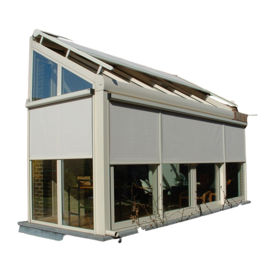
VERANDA HRV52
1. INTRODUCTION
Veranda HRV52 is an outside sun protection to be fitted on top of the Veranda. This sun protection blocks the sun rays
and in doing so protects the veranda against overheating. Thanks to the special and manyfold fastening accessories, this
sun protection can be fitted onto all existing Veranda profiles..
Veranda has been designed as a sun protection and for that reason may not be used as an all-weather
protection. In case of heavy rain or wind the sun-blind has to be closed immediately. Therefore we recommend
to use the sun protection in combination wth an automated wind/sun – control.
2. GENERAL WARNINGS
For a safe fitting, use and maintenance of this sun protection a number of precautions have to be taken. For the
safety of everyone concerned, please do take notice of the following general warnings!
This manual is meant to be used by professionals only! It is not to be used by DIY-enthusiasts or apprentice fitters.
Before you start, please do read these instructions thoroughly.
The tightening of springs creates important powers. Be very careful and make sure of a solid footing whilst operating.
Provide sufficient light in the fitting area. Dispose of obstacles and dirt. Make sure that, except for the fitters, no other
people are in the fitting area. Unauthorized people might be in the way or at risk themselves.
Whilst operating the system, you must be able to overlook the complete area and the whole of the sun protection. There
are a number of places where people might get injured. Especially watch the following parts where people might risk
getting jammed: the extension pole, the intermediate rollers, the bench, the guide rails and the casing.
Electrical connections have to be made in accordance with the existing local norms and requirements.
3. LIST OF REQUIREMENTS
•
Ladder
•
Footplanks
•
Wooden blocks 60x60x300 mm
•
Electric drill
•
Cross-head screwdriver
•
Fork or ring spanners 13
•
Tongs for clinch-nails
•
Metal drill
•
Ruler and pencil
•
Voltmeter or test lamp 220 V
•
Masonry drill 6 mm
•
Clamps for electric wire
•
Test cable with switch
•
Socket wrench 4 mm
Validity of the manual: 1. 3. 2018
MEASUREMENT AND ASSEMBLY MANUAL
1
Advertisement

Subscribe to Our Youtube Channel
Related Manuals for Isotra VERANDA HRV52


Summary of Contents for Isotra VERANDA HRV52
- Page 1 1. INTRODUCTION Veranda HRV52 is an outside sun protection to be fitted on top of the Veranda. This sun protection blocks the sun rays and in doing so protects the veranda against overheating. Thanks to the special and manyfold fastening accessories, this sun protection can be fitted onto all existing Veranda profiles..
- Page 2 MEASUREMENT AND ASSEMBLY MANUAL 4. ASSEMBLY INSTRUCTIONS 4.1. OPENING THE PACKAGING Take the bag of accessories, and divide the attachment points by the number of guide rails supplied. Make sure each guide rail has the same number of supports. The attachment points: Standard aluminium supports Higher aluminium supports Push the hexagonal screws in the lateral guide and fix the aluminium supports.
- Page 3 MEASUREMENT AND ASSEMBLY MANUAL 4.6. POSITIONING THE WOODEN BLOCKS Take a few blocks (60x60x300 mm.) and slide them under the mounting brackets between the boxes and the Veranda profile. 4.7. CONNECTING THE BOXES Take care that the spindles are matched to each other correctly. The slots for the fabrics must be in line with each other.
- Page 4 MEASUREMENT AND ASSEMBLY MANUAL 4.11. POSITIONING THE BOX AND THE GUIDE RAILS Now lay the guide rails onto the glass roof, just in front of the pins of the mounting brackets. Make sure that the pins of the mounting brackets on the box are in line with the guide rails. 4.12.
- Page 5 MEASUREMENT AND ASSEMBLY MANUAL 4.16. TENSIONING THE SPRING Position the end profile in the highest position and make 2 marks in the end profile the distance apart R shown in the separate table. The maximum distance depends on the spring supplied, the used fabric, the diameter of the roll for fabric and the extension of the blind.
- Page 6 MEASUREMENT AND ASSEMBLY MANUAL 4.19. CHECKING THE RIGHT ANGLES The Veranda is now in its lowest position. Screw down the base supports permanently. The guide rails and the box should stand at right angles to each other. You can check this by using a large try square or the 60-80-100 rule as shown in figure.
- Page 7 MEASUREMENT AND ASSEMBLY MANUAL 5.1. FLOW CHART FOR A SINGLE-POLE SWITCH There are 4 wires from the motor. Yellow-green (earth), blue (neutral), brown and black (raise and lower). From the fuse box, there are 3 wires. Yellow-green (earth), blue (neutral), and phase. Connect the wires as shown in the diagram.
- Page 8 MEASUREMENT AND ASSEMBLY MANUAL 6. FAULT-FINDING 6.1. VERANDA WILL NOT UNROLL OR ROLL UP The internal final switch points at zero in both directions. Push both adjusting buttons of the motor and continue adjusting the final switch. Wire making poor contact after extending motor cable. Check connections. Motor has run hot.
- Page 9 MEASUREMENT AND ASSEMBLY MANUAL 6.7. FABRIC NOT TAUT AT BOTTOM The guide rails are not straight with respect to the box. Cable sticking somewhere. Spring not under sufficient tension. Faulty adjustment of limit switches. End profile runs against the pulleys of the guide rails. 6.8.
- Page 10 MEASUREMENT AND ASSEMBLY MANUAL 7. METHOD FOR COUPLING 2 GUIDE RAILS In some cases we have to couple 2 guide rails (when 2 or more systems are mounted beside one another). This can be done in different ways. 7.1. MOUNTING THE BASE ATTACHMENT POINT IN THE MIDDLE The coupling plate is fixed directly underneath both guide rails.
- Page 11 MEASUREMENT AND ASSEMBLY MANUAL 7.3. MOUNTING THE ATTACHMENT POINT UNDERNEATH THE LEFT OR THE RIGHT GUIDE RAIL The coupling plate is fixed in front of or behind the used attachment point. Validity of the manual: 1. 3. 2018...
Need help?
Do you have a question about the VERANDA HRV52 and is the answer not in the manual?
Questions and answers