
Related Manuals for Leuze BPS 34


Summary of Contents for Leuze BPS 34
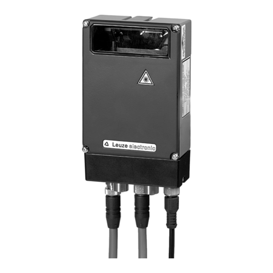
- Page 1 Original operating instructions BPS 34 Bar code positioning system - PROFIBUS DP We reserve the right to make technical changes EN • 2021-01-08 • 50105437...
- Page 2 © 2021 Leuze electronic GmbH & Co. KG In der Braike 1 D-73277 Owen / Germany Phone: +49 7021 573-0 Fax: +49 7021 573-199 http://www.leuze.com info@leuze.com Leuze electronic GmbH + Co. KG BPS 34...
-
Page 3: Table Of Contents
Technical data of BPS 34........ - Page 4 10.1 Type overview: BPS 34 ........
-
Page 5: General Information
This symbol indicates text passages containing important information. Declaration of Conformity The bar code positioning system BPS 34, the modular connector hood MS 34 103/MS 34 105, and the optional modular service display MSD 1 101 have been developed and manufactured in accordance with the applicable European standards and directives. -
Page 6: Safety
Safety Safety The bar code positioning systems of the BPS 34 series and the MS 34 10x modular connector hoods have been developed, produced and tested subject to the applicable safety standards. They correspond to the state of the art. -
Page 7: Foreseeable Misuse
Do not carry out modifications or otherwise interfere with the device. The device must not be tampered with and must not be changed in any way. The use of a bar code tape not approved by Leuze is equivalent to an intervention in or change to the device/measurement system. -
Page 8: Laser Safety Notices
The device must not be tampered with and must not be changed in any way. There are no user-serviceable parts inside the device. Repairs must only be performed by Leuze electronic GmbH + Co. KG. NOTE Affix laser information and warning signs! Laser information and warning signs are attached to the device (see Figure 2.1):... -
Page 9: Fast Commissioning Steps At A Glance
Description of the BPS 34 functions The BPS 34 uses visible red laser light to determine its position relative to the bar code tape. This essen- tially takes place in three steps: Reading a code on the bar code tape... - Page 10 Connecting the voltage supply and PROFIBUS The BPS 34, in combination with an MS 34 103 or MS 34 105, is connected via M12 connectors. Connecting the voltage supply The voltage supply is connected via the PWR IN M12 connection.
- Page 11 Figure 3.5: Example PROFIBUS manager Store the slave address for the BPS 34 in the PROFIBUS manager. Ensure that the address is the same as the address configured in the device. Connecting the switching input/switching output to the BPS 34 ...
-
Page 12: Technical Data Of Bps 34
Technical data of BPS 34 Technical data of BPS 34 General specifications BPS 34 Optical data Light source Laser diode Beam deflection Via rotating polygon wheel Reading distance See reading field (Figure 4.3.5) Optical window Glass with scratch-resistant indium coating Laser class 2 acc. -
Page 13: Dimensioned Drawings
For devices with integrated heating (…H models), window heating is in constant operation. Regulation of device-internal heating is temperature dependent. Dimensioned drawings BPS 34 SM 100 / BPS 34 SM 100 H / BPS 34 SM 100 HT Rear view Top view... -
Page 14: Electrical Connection
Technical data of BPS 34 Electrical connection The BPS 34 can be connected via the MS 34 103/MS 34 105 using M12 connectors. For the locations of the individual device connections, please refer to the device detail shown in Figure 4.3. -
Page 15: Pwr In - Voltage Supply And Switching Input/Output
Figure 4.4: Pin assignment - PWR IN Connecting the functional earth PE BPS 34 with MS 34 103/MS 34 105 connector hood: Connect PE to PIN 5 of the M12 connector PWR IN for voltage supply! NOTE Programming of the switching input/switching output is performed via module 7 (Switching input) and module 8 (Switching output). -
Page 16: Dp In - Profibus Dp Incoming
Technical data of BPS 34 4.3.2 DP IN - PROFIBUS DP incoming DP IN (5-pin plug, B-coded) Name Comment 5VDC for bus termination DP IN A (N) A (N) Receive/transmit data A-line (N) Functional earth for bus termination GND 3... -
Page 17: Sw In/Out - Switching Input/Switching Output
Technical data of BPS 34 4.3.4 SW IN/OUT – Switching input/switching output SW IN/OUT (5-pin socket, A-coded) Name Comment Supply voltage for sensor system (VOUT identical to VIN at PWR IN) VOUT SW IN/OUT Without optics heating: +10 … +30VDC SWOUT With optics heating: +22 …... -
Page 18: Bps 34 Reading Field Curve
Technical data of BPS 34 Connecting the switching input / switching output The BPS 34 is provided with a switching input and a switching output. The connection is performed as shown in Figure 4.8: SW IN/OUT connector SWIN V OUT... -
Page 19: Connection Units Ms 34
MS 34 103 and MS 34 105 modular connector hoods A modular connector hood of type MS 34 103 or MS 34 105 is part of every BPS 34. The two connector hoods are used to connect the BPS 34 to the PROFIBUS. For this, they feature one DP IN and one DP OUT connection each, as well as switches for address setting. -
Page 20: Dimensioned Drawings
It indicates the state of the PROFIBUS connection. State Meaning Voltage off or device not yet recognized by the PROFIBUS Green, flashing Initialization of the device, establishing the PROFIBUS communication Green, continuous light Data operation Leuze electronic GmbH + Co. KG BPS 34... - Page 21 Orange, continuous light Service operation active 2) Note: The LED remains off until the BPS 34 is recognized by the PROFIBUS. Only after the PROFIBUS has addressed the BPS 34 for the first time, the following state descriptions apply. Leuze electronic GmbH + Co. KG...
-
Page 22: Bar Code Tape
No shrinkage, tested according to DIN 30646 Curing Final curing after 72 h, the position can be detected immediately by the BPS 34 after the BCB is affixed Heat expansion Due to the high elasticity of the BCB, heat expansion of the base... -
Page 23: Mounting The Bar Code Tape
BPS. The gap must not be greater than the distance from one cut mark to the next (max. one label). max. 40 mm 000020 000024 000028 000032 000036 Cut mark Figure 6.3: Gap in the cut bar code tape Leuze electronic GmbH + Co. KG BPS 34... - Page 24 If the scan- ning beam cannot completely scan any label, the BPS 34 returns the value 0. As soon as the BPS 34 can again scan a complete label, it calculates the next position value.
-
Page 25: Control Bar Codes
Control bar codes With the aid of control bar codes, which are simply affixed over the bar code tape at the necessary posi- tions, functions can be activated and deactivated in the BPS 34. Structure of the control bar codes The control bar codes utilize code type Code128 with character set B;... -
Page 26: Controllable Functions
If the center of the BPS 34 reaches the transition point of the control bar code, the device switches to the second tape, provided the next position label is in its scanning beam. As a result, the output position can always be uniquely associated with one tape. -
Page 27: Repair Kit
If only the "MVS" label is located in the scanning beam, the voltage on the BPS 34 must not be switched off. Otherwise the BPS 34 will return a position value of zero when the voltage is switched back on. - Page 28 4 cm. Figure 6.9: Printer settings for BCB repair kit 40 mm 000020 000024 000028 000032 000036 Figure 6.10: Checking the print results of the BCB repair kit Leuze electronic GmbH + Co. KG BPS 34...
-
Page 29: Mounting
BT 56 mounting device The BT 56 mounting device is available for mounting the BPS 34 using the fastening grooves. It is designed for rod mounting (Ø 16 mm to 20 mm). For order guide, please refer to Chapter 10.5 on Page 71. -
Page 30: Device Arrangement
• On the BPS 34, the beam is not emitted perpendicular to the cover of the housing, but with an angle of 10° towards the top. This angle is intended to prevent total reflection on the bar code tape. This beam exit is already integrated in the device. -
Page 31: Mounting The Bar Code Tape
Mounting the bar code tape The BPS 34 and bar code tape combination is mounted in such a way that the scanning beam is uninter- rupted and is incident on the bar code tape as described in Figure 7.4 on Page 31. - Page 32 Mounting NOTE For further information on mounting the bar code tape, please refer to Chapter 6.3 on Page 23. Leuze electronic GmbH + Co. KG BPS 34...
-
Page 33: Device Parameters And Interfaces
8.1.1 General information The BPS 34 with MS 34 103/MS 34 105 is designed as a PROFIBUS device (PROFIBUS DP-V0 acc. to IEC 61784-1) with a baud rate of 12MBd. The functionality of the device is defined via parameter sets which are clustered in modules. - Page 34 Chapter 10.7 on Page 72. The BPS 34 can be used in combination with an MS 34 103/MS 34 105 to branch out the PROFIBUS network. The continuing network is connected via DP OUT.
-
Page 35: Profibus Address
You can find the GSD file at www.leuze.com. This file stores all the data required for the operation of the BPS 34. This data consists of device parame- ters required for the operation of the BPS 34 and the definition of the control and status bits. If parameters are changed in the project tool, for example, these changes are stored in the project, not in the GSD file. -
Page 36: Overview Of The Gsd Modules
Device parameters and interfaces The modules fall into the following categories: • Parameter module for the configuration of the BPS 34. • Status or control modules that influence the input/output data. • Modules that may include both parameters and control or status information. - Page 37 (I) Range state (outside of measurement range) (I) Preset active (I) Dynamic preset teach Status Page 53 (I) State (I) Position limit value status 1 (I) Position limit value status 2 (I) Standby status Leuze electronic GmbH + Co. KG BPS 34...
- Page 38 (O) Reset to factory settings (I) Current speed Speed Page 59 (P) Resolution (P) Scaling factor Speed parameters (P) Integration depth Page 60 (P) Tolerance time (on error message) (P) Error output delay Leuze electronic GmbH + Co. KG BPS 34...
- Page 39 (P) Switching type (value is above or below the defined limits) Static speed limit values Page 64 (for limit value 1 … 4) (P) Speed limit value (P) Hysteresis (P) Range start (P) Range end Leuze electronic GmbH + Co. KG BPS 34...
-
Page 40: Detailed Description Of The Modules
– – Sign 1: Sign + magnitude Parameter length: 1 byte Hex coding of module 1 "Position value" The value listed in the table shows the hex coding of the default settings. Leuze electronic GmbH + Co. KG BPS 34... - Page 41 None 8.1.7.2 Module 2: Resolution Description With this module, the resolution for the position value of module 1 is defined. The BPS 34 also performs a rounding correction (The position value is divided by the defined value range). NOTE The resolution only determines the mathematical decimal value and has no effect on the measurement accuracy.
- Page 42 The preset remains stored in the BPS 34 and remains active even following a new start. In order for the BPS 34 to again output the position value without the preset, bit 0.1 in the output data must be set.
- Page 43 The preset remains stored in the BPS 34 and remains active even following a new start. In order for the BPS 34 to again output the tape value, bit 0.1 in the output data must be set (preset reset).
- Page 44 Underlined in the CR column are the modules which must be activated in addition to the current module. Description The scaling function is used to convert the tape values to any unit of measurement. To do this, the tape value is multiplied by the scaling factor. Leuze electronic GmbH + Co. KG BPS 34...
- Page 45 NOTE Underlined in the CR column are the modules which must be activated in addition to the current module. Description The module defines the mode of operation of the digital switching input. Leuze electronic GmbH + Co. KG BPS 34...
- Page 46 13: Start speed measurement 14: Stop speed measurement Parameter length: 10 byte Hex coding of module 7 "Switching input" The value listed in the table shows the hex coding of the default settings. Leuze electronic GmbH + Co. KG BPS 34...
- Page 47 The parameter defines the switch-on time period for the Pulse duration unsign16 0 … 1,300 – switching output. If the value in [ms] is 0, the signal is static. Leuze electronic GmbH + Co. KG BPS 34...
- Page 48 OR. Hex coding of module 8 "Switching output" The value listed in the table shows the hex coding of the default settings. 01 90 04 00 08 00 Input data None Leuze electronic GmbH + Co. KG BPS 34...
- Page 49 0 … 65,535 10,000 – [ms] Parameter length: 4 byte Hex coding of module 9 "Control" The value listed in the table shows the hex coding of the default settings. 27 10 Leuze electronic GmbH + Co. KG BPS 34...
- Page 50 8.1.7.10 Module 10: Measurement value acquisition Description With this module, a working range on the bar code tape can be defined. The BPS 34 outputs position values within these minimum and maximum limits. Outside of these limits, a position value of zero is output.
- Page 51 In order to obtain positive or negative position values depending on the direction of movement of the BPS 34, the counting direction can be selected as normal or inverted in the output data of this module. In order to obtain more exact measurement data while in the static state or for very slow travel speeds, the integration depth can be increased here.
- Page 52 Output data length: 1 byte NOTE The BPS 34 is set as follows by default: The position value is output with "normal" counting direction. With the "inverted" counting direction, 10,000,000mm minus the position value is output. This behavior can be influenced using the "Static preset"/"Dynamic preset"...
- Page 53 8.1.7.12 Module 12: Status NOTE Underlined in the CR column are the modules which must be activated in addition to the current module. Description This module supplies various BPS 34 status information to the PROFIBUS master. Parameter None Input data Input data Description Rel.
- Page 54 With "MinMax reset", the input data are reset to 155812h. With this module, the settings for the Preset (module 3), Offset (module 5) and Scaling (module 6) modules must be taken into account. Leuze electronic GmbH + Co. KG BPS 34...
- Page 55 The limit value function compares the output position value with a position stored during configuration. If the value is above or below the limit value, the limit value status 2 (module 12) is set and, if configured, the switching output (module 8) is appropriately set. Leuze electronic GmbH + Co. KG BPS 34...
- Page 56 1 in module 12 is set and, if configured, the switching output is appro- priately set. The limit value is transferred to the BPS 34 together with the output data of this module by the PROFIBUS master.
- Page 57 2 in module 12 is set and, if configured, the switching output is appro- priately set. The limit value is transferred to the BPS 34 together with the output data of this module by the PROFIBUS master.
- Page 58 The availability of the system is thereby ensured. No new values are delivered by the BPS 34, however, for a period of time extending up to the configured tolerance time. With the "delay error output" parameter, an integration error (corresponds to a missing position value) can be signaled immedi- ately or after the tolerance time has elapsed.
- Page 59 Description The "service" function is used to reset the parameter set of the BPS 34 to default settings. This reset only occurs directly in the BPS 34. After the reset function has been activated, the device carries out a reset and is freshly configured on the PROFIBUS.
- Page 60 Outputs the current speed with the configured resolution and the desired scaling factor. In order for the speed to be calculated in the BPS 34 and output in this module, module 22 (Control speed measurement) must also be activated in the PROFIBUS project.
- Page 61 4 (default) Hex coding of module 21 "Speed parameters" The value listed in the table shows the hex coding of the default settings. 03 E8 00 32 Input data None Output data None Leuze electronic GmbH + Co. KG BPS 34...
- Page 62 • Init: Base setting during initial startup of the BPS 34 • Idle: The BPS 34 is in idle state (scanning beam is off, but motor is running) • Measure: The BPS 34 is in measurement state (data are output in module 1) •...
- Page 63 – values. speed reset Output data length: 1 byte 8.1.7.23 Module 23: Speed measurement status Description This module supplies various status information regarding the speed measurement of the BPS 34 to the PROFIBUS master. Parameter None Input data Input data Description Rel.
- Page 64 "5000", the direction-dependent check is only performed in the direction from "5500" to "5000". If the check is independent of direction, the order of range start and end is without meaning. If the Leuze electronic GmbH + Co. KG BPS 34...
- Page 65 -10,000,000 … 10,000,000 value 3 in [mm] position. The speed limit value is Range end limit sign32 -10,000,000 … 10,000,000 monitored up to this position. value 3 in [mm] Leuze electronic GmbH + Co. KG BPS 34...
- Page 66 Input data None Output data None 8.1.7.26 Module 26: Dynamic speed limit value NOTE Underlined in the CR column are the modules which must be activated in addition to the current module. Leuze electronic GmbH + Co. KG BPS 34...
- Page 67 PROFIBUS master. The transferred values are acti- vated by bit 0.0, i.e. if this bit is set, the BPS 34 compares the current speed with the new limit value condi- tions.
- Page 68 Hex coding of module 27 "Tape value correction" The value listed in the table shows the hex coding of the default settings. 27 10 00 00 00 00 00 98 96 80 Input data None Output data None Leuze electronic GmbH + Co. KG BPS 34...
- Page 69 Note: The LED remains off until the BPS 34 is recognized by the PROFIBUS. Only after the PROFIBUS has addressed the BPS 34 for the first time, the following state descriptions apply. LED MS 34 10x = • Error on the PROFIBUS.
- Page 70 Diagnostics and troubleshooting Customer data (please complete) Leuze service fax number: +49 7021 573-199 Device type: Company: Contact person/department: Phone (direct dial): Fax: Street / no.: ZIP code / City: Country: Leuze electronic GmbH + Co. KG BPS 34...
- Page 71 Type designation Comment 50038007 BPS 34 S M 100 PROFIBUS DP interface, UL approval 50038008 BPS 34 S M 100 H PROFIBUS DP interface and heating, no UL approval 50103179 BPS 34 S M 100 HT PROFIBUS DP interface, max. temp up to 50 °C...
- Page 72 Accessories - Ready-made cables for PROFIBUS connection 10.7.1 General • Cable KB PB… for connecting to the DP IN/DP OUT M12 connector • Standard cables available in lengths from 2 … 30m • Special cables on request. Leuze electronic GmbH + Co. KG BPS 34...
- Page 73 KD PB-M12-4A-P3-300 M12 socket for DP IN, axial plug outlet, open cable end, cable length 30m 50135247 KS PB-M12-4A-P3-020 M12 plug for DP OUT, axial plug outlet, open cable end, cable length 2m Leuze electronic GmbH + Co. KG BPS 34...
- Page 74 • Special tapes longer than 300 m are delivered wound on multiple rolls. An entry wizard is available for special tapes on the Leuze website under the "BPS 34 - Accessories" heading. The entry wizard provides support when entering the individual pieces of tape data and creates a query or order form with the correct part number and type designation.
- Page 75 • Twin special tapes longer than 300 m are delivered wound on multiple rolls. An entry wizard is available for twin special tapes on the Leuze website under the "BPS 34 - Accessories" heading. The entry wizard provides support when entering the individual pieces of tape data and creates a query or order form with the correct part number and type designation.
- Page 76 Contact your Leuze distributor or service organization should repairs be required. The addresses can be found on the inside of the cover and on the back. NOTE When sending devices to Leuze electronic for repair, please provide an accurate description of the error. 11.3...
- Page 77 Appendix Appendix 12.1 EC Declaration of Conformity Leuze electronic GmbH + Co. KG BPS 34...
- Page 78 ......19 MS 34 103 Leuze electronic GmbH + Co. KG BPS 34...
- Page 79 ....... 33 GSD file Leuze electronic GmbH + Co. KG BPS 34...
- Page 80 ......18 Working range Leuze electronic GmbH + Co. KG BPS 34...
Need help?
Do you have a question about the BPS 34 and is the answer not in the manual?
Questions and answers