Advertisement
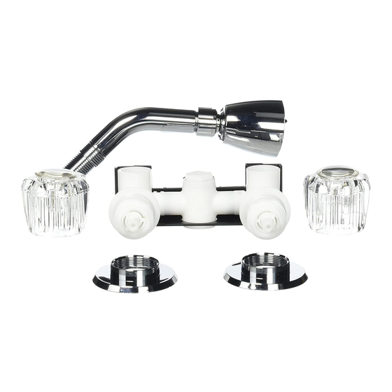
VALVE & SHOWER HEAD ASSEMBLY
Installation of this shower valve and spray head requires that 4 (four) 1" diameter holes be drilled into the shower
cabinet side wall, three holes are required for mounting the control valve, the remaining hole is for the spray head.
See Figure 1 for control valve hole spacing; the spray head can be mounted at any desired height. The shower
cabinet side wall can be easily drilled using a power drill and 1"diameter hole saw. All pipe fitting connections require
1/2"-14NPSM threads. Refer to PARTS ILLUSTRATION on back.
SHOWER HEAD
1.
The shower head is equipped with a built-in flow restrictor, for water conservation. This will limit the flow of water
to 2.0 GPM@80 PSI.
2.
Wrap two turn of 1/2" wide teflon tape (obtainable at most hardware/plumbing stores) on the shower arm.
(3)Wrap the tape in a clockwise direction.
Slide the flange nut (4) onto the shower arm.(3) Hand tighten until a snug fit is obtained.
3.
Screw the shower head (2)onto the shower arm/flange nut assembly. Hand tighten until a snug fit is obtained.
4.
CONTROL VALVE
1.
Wrap two turns of 1/2" wide teflon tape on the three threaded shanks of the control valve(1).Wrap the tape in
a clockwise direction.
2.
From the inside of the shower cabinet, insert the threaded shanks of the control valve through the pre-drilled
mounting holes, secure on outside with locknuts. Hand tighten until a snug fit is obtained.
Make water hook-up and riser connection in full compliance with local code requirements.
SI-248(01-16)
MODEL NO. 68.600 HW
1" DIA.,3 HOLES REQ'D
FIG.1
NOTE: Do not use pipe dope or other
petroleum based compounds in place of
the teflon tape specified, or on any of the
shower or faucet components.
Advertisement
Table of Contents

Subscribe to Our Youtube Channel
Related Manuals for Mustee 68.600 HW


Summary of Contents for Mustee 68.600 HW
- Page 1 VALVE & SHOWER HEAD ASSEMBLY MODEL NO. 68.600 HW Installation of this shower valve and spray head requires that 4 (four) 1” diameter holes be drilled into the shower cabinet side wall, three holes are required for mounting the control valve, the remaining hole is for the spray head.
- Page 2 MODEL NO.68.600 HW PARTS ILLUSTRATION ● NOTE: All threaded connections are 1/2”-14 NPSM Thread PARTS LIST Should you have any questions with this Key No. Part No. Description shower valve please 04A005W Control Valve Body -4” Ctrs. contact us at:...
Need help?
Do you have a question about the 68.600 HW and is the answer not in the manual?
Questions and answers