Table of Contents
Advertisement
Quick Links
Advertisement
Table of Contents

Subscribe to Our Youtube Channel
Related Manuals for IDK HDC-TH200


Summary of Contents for IDK HDC-TH200
- Page 1 HDBaseT Extender HDC-TH200 <User’s Guide> Ver.1.1.0 ● Thank you for choosing our HDBseT Extender. ● To ensure the best performance of this product, please read this User’s Guide fully and carefully before using it and keep this manual beside the product.
- Page 2 HDC-TH200 User’s Guide Trademarks ● Blu-ray Disc are trademarks of Blu-ray Blu-ray Disc Association ● The terms HDMI and HDMI High-Definition Multimedia Interface, and the HDMI Logo are trademarks or registered trademarks of HDMI Licensing, LLC in the United States and other countries.
- Page 3 HDC-TH200 User’s Guide Before reading this manual ● All rights reserved. ● This Users guide is subject to change without notice. You can download the latest version from IDK’s website at: http://www.idk.co.jp/en/index.html FCC STATEMENT This equipment has been tested and found to comply with the limits for a Class A digital device, pursuant to part 15 of the FCC Rules.
- Page 4 HDC-TH200 User’s Guide Safety instructions Read and understand all safety and operating instructions before using this product. Follow all instructions and cautions as detailed in this document. Enforcement Symbol Description Indicates the presence of a hazard that may result in death or serious...
- Page 5 The product is intended to be installed by skilled technicians. For installation, please contact a system integrator or IDK. Otherwise, it may cause fire, electric shock, injury, or property damage. Set the power plug in a convenient place to unplug easily.
- Page 6 HDC-TH200 User’s Guide Caution Do not place the product in any place where it will be subjected to high temperatures. If the product is subjected to direct sunlight or high temperatures, it may cause fire. Do not place the product in humid, oil smoke, or dusty place.
- Page 7 HDC-TH200 User’s Guide Altitude: Do not place the product at elevations of 2,000 meters (6562 feet) or higher above sea level. Failure to do so may shorten the life of the internal parts and result in malfunctions. Instruction...
-
Page 8: Table Of Contents
Twisted pair cable ........................18 6.3.3 DIN plug AC adapter .......................19 6.3.4 Analog video input connector ....................21 6.3.5 Connection between HDC-TH200 and MSD-402 ..............21 Basic operation............................22 Menu operations ..........................22 Locking menu operation keys ......................23 Initialization ............................23 Menus ..............................24 Menu list ............................25 Input switching setting ........................28... - Page 9 HDC-TH200 User’s Guide 8.5.2 [ F40 ] Analog video automatic adjustment ................44 8.5.3 [ F42 ] Setting the total number of holizontal dots..............46 8.5.4 [ F43 ] Starting position of holizontal dots ................47 8.5.5 [ F44 ] Holizontal Active area ....................47 8.5.6...
-
Page 10: Included Items
HDC-TH200 User’s Guide 1 Included items Make sure all items below are included in the package. If any items are missing or damaged, please contact IDK. One (1) HDC-TH200 (main unit) One (1) DIN plug AC adapter with locking One (1) cord clamps... -
Page 11: Product Outline
HDC-TH200 User’s Guide 2 Product outline The IDK HDC-TH200 is a transmitter for long-distance transmission of HDMI/DVI and Analog (video and audio) input signals over a twisted pair cable. Since HDMI/DVI signals are transmitted without compression or processing, the image quality can be kept. -
Page 12: Features
HDC-TH200 User’s Guide 3 Features ■ Video ・Up to QWXGA (RB)*1 or 1080p ・HDCP supported ・3D Y/C separation for NTSC and PAL signals ・Digital cable EQ INPUT: up to 33 ft. to 98.43 ft. / 10 m to 30 m ・Up to 328.08 ft. -
Page 13: Panels
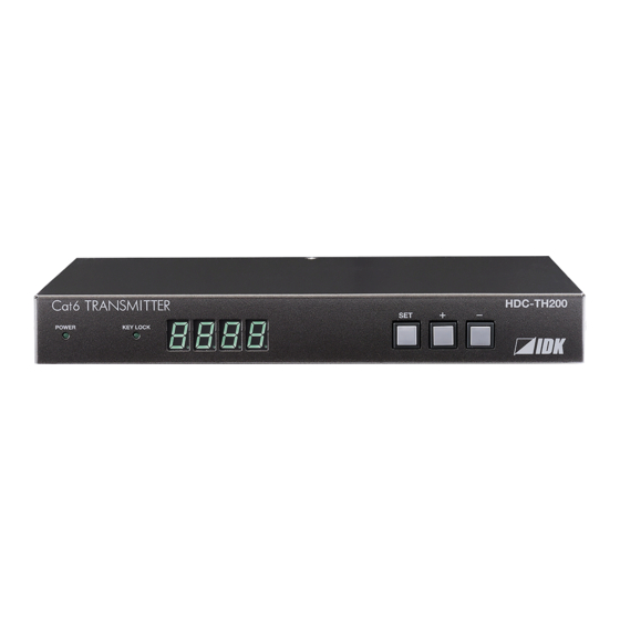
HDC-TH200 User’s Guide 4 Panels 4.1 Front panel ① ② ③ ④ [Fig. 4.1] Front panel drawing [Table 4.1] Front panel’s part name and description Part name Description ① POWER LED Shows power status of the HDC ON: Power is supplied to the HDC OFF: Power is not supplied to the HDC ②... -
Page 14: Rear Panel
HDC-TH200 User’s Guide 4.2 Rear Panel ① ② ③ ④ ⑤ ⑥ ⑦ ⑧ ⑨ ⑩ [Fig. 4.2] Rear panel drawing [Table 4.2] Rear panel’s part name and description Part name Description ① POWER LED Shows power status of the HDC... -
Page 15: Example Connection
HDC-TH200 User’s Guide 5 Example connection HDMI / DVI HDMI / DVI HDBaseT Cat6 Tx for HDMI HDC-TH100-C Cat6 Rx for HDMI HDC-RH100-C Up to 6.56 ft. / 2 m Up to 6.56 ft. / 2 m Up to 330 ft. / 100 m... -
Page 16: Precautions
HDC-TH200 User’s Guide 6 Precautions Before connecting to external devices, follow the precautions below. 6.1 Installing rubber feet Please clean up the HDC main unit, and then install rubber feet to the four corners of the MSD. 6.2 Installation When installing the HDC, please observe the following precautions. -
Page 17: Cabling
Removing HDMI cable and cable clamp ① ② ③ ④ Pull out while pressing [Fig. 6.2] Attaching a cable clamp 6.3.1 Cables IDK Corporation provides various digital cables such as HDMI, DVI, and twisted pair cables. Please choose appropriate cables for your system configuration. -
Page 18: Twisted Pair Cable
50 m/164.04 ft. Cat6 * CAT.5E HDC cable developed by IDK Corporation is double shielded twisted pair cable for high quality video transmission. It protects video signal from external noise or other interferences by having double shielded structure. Its transmission characteristic meets 500 MHz up to 100 m/328.08 ft., and it is certified and recommended by HDBaseT alliance. -
Page 19: Din Plug Ac Adapter
HDC-TH200 User’s Guide 6.3.3 DIN plug AC adapter ■ Attaching/removing AC plug The AC plug for DIN plug AC adapter is different by each country. Please use appropriate AC plug. Removing: Removes AC plug by sliding AC plug from AC adapter main unit whole holding down the partial knob ②... - Page 20 HDC-TH200 User’s Guide ■ Connecting DC plug Please connect DC plug to the MSD until you can hear small sound of fixing. When you disconnect DC plug from the MSD, please hold the part which is specified in following figure.
-
Page 21: Analog Video Input Connector
N.C.:No Connection 6.3.5 Connection between HDC-TH200 and MSD-402 When HDC-TH200 is connected to the MSD-402 using HDBaseT signal, its input channels can be switched from the MSD-402. For the details please see User’s Guide of MSD-402. 【See:5 Example connection (P.15) 】... -
Page 22: Basic Operation
HDC-TH200 User’s Guide 7 Basic operation 7.1 Menu operations You can set all input/output settings of video and audio signals from menu operation keys. Menu operation keys Select the menu number first and then select the setting number. If you do not operate for 10 seconds in step 5, you will go back to step 2. -
Page 23: Locking Menu Operation Keys
HDC-TH200 User’s Guide 7.2 Locking menu operation keys Press and hold the “SET” key for 3 seconds or longer to set/cancel key lock. Menu operation keys will be locked by pressing the “SET” key for three seconds. Blinking (Unlock) (During lock setting) -
Page 24: Menus
HDC-TH200 User’s Guide 8 Menus Setup menus: setting video and audio signals in normal use Maintenance menus: checking operation Status display menus: displaying statuses of input signals and connection with sink devices Note: Normally, the maintenance menu and status display menu are not displayed as a default. -
Page 25: Menu List
HDC-TH200 User’s Guide 8.1 Menu list ■ Setup menu [Table 8.2] Setup menus (1/2) Setting Menu number and functions Page Setting value Dafault ― [ F00 ] Manual input channel switching Digital input / Analog input [ F01 ] Copying EDID... - Page 26 HDC-TH200 User’s Guide [Table 8.3] Setup menus (2/2) Setting Menu number and functions Page Setting value Default [ F40 ] Analog video automatic adjustment No auto adjustmnet / Auto Auto adjustment mode 1 / adjustment Auto adjustment mode 2 mode 1 -...
- Page 27 HDC-TH200 User’s Guide ■ Maintenance menus [Table 8.4] Maintenance menus Setting Menu number and functions Page Setting value Default [ C01 ] Setting sink device EDID check When Always recognize as EDID read HDMIdevice / When EDID read error, error, recognize as HDMI device...
-
Page 28: Input Switching Setting
HDC-TH200 will switch input channel under following conditions: ・ When new video signal is detected, HDC-TH200 switch the input channel to the detected channel ・ When current selected channel loose signal and if another channel has video signal, HDC-TH200 switch the input channel to the channel which has video image. -
Page 29: F06 ] Audio
HDC-TH200 User’s Guide 8.2.2 [ F06 ] Audio Select audio which is embedded to video signal Set value 00 : Auto (following video input) [Default] 01 : Digital audio (HDMI input connector) 02 : Analog audio (analog audio input connector) 【NOTE】... -
Page 30: F00 ] Manual Input Channel Switching
HDC-TH200 User’s Guide 8.2.3 [ F00 ] Manual input channel switching You can switch input channel from front panel menu. “ – “ is assigned to digital input channel and “ + “ is assigned to analog input channel. During this menu is displayed automatic switching set by 8.2.1 [ F05 ] Priority of input channel automatic switching (P.28) is disabled temporary. -
Page 31: Input Settings
HDC-TH200 User’s Guide 8.3 Input settings 8.3.1 [ F16 ] No-signal input monitoring If you change the settings of EDID of the HDC or turn off/on the HDC, the source device may not output video signal. Use this menu to set the monitoring time which is from when a source device stops outputting signal to when the HDC requests the source device to output video signal. -
Page 32: F07 ] Analog Input Signal Type
HDC-TH200 User’s Guide 8.3.3 [ F07 ] Analog input signal type You can set video type which is input to analog input connector. If there is no video input on analog input connector, “ - - - ” will be displayed. -
Page 33: Edid
HDC-TH200 User’s Guide 8.4 EDID 8.4.1 [ F01 ] Copying EDID EDID of sink devices can be read and stored, and the copied EDID can apply in the same way of internal EDID. Set value on:Copying EDID oFF:Not copying EDID... -
Page 34: F10 To F11 ] Setting Edid Resolution
EDID for digital input and analog input can be set individually. “01 to 02” [ F10 ] : Can be selected only for digital input “03 to 22” are internal EDID which HDC-TH200 has. Menu number F10 : Digital input... -
Page 35: F76 To F77 ] Setting Edid Wxga
HDC-TH200 User’s Guide [Table 8.7] The maximum resolution and EDID supported pixels EDID supported Pixels Max. resolution (Setting values) 1080p(59.94/60) 720p 1080i 1080p (24/25/30p/50p) 800x600 1024x768 1280x720 1280x768 1280x800 1280x960 1280x1024 1360x768 ※ 1400x1050 1440x900 1600x900 1600x1200 1680x1050 1920x1080 1920x1200 2048x1152 Y:Supported, N:Not supported... -
Page 36: F20 ] Setting Deep Color
HDC-TH200 User’s Guide 8.4.4 [ F20 ] Setting Deep Color You can set the Deep Color (color depth) that is output from the source device. Set value 08: 8 bit [Default] 10: 10 bit 12: 12 bit 【NOTE】 This setting is only for digital input EDID. The setting will be applied only if one of 03 to 22 is selected for 8.4.2 [ F10 to F11 ] Setting EDID resolution (P.34). -
Page 37: F24 ] Setting Ac-3 Dolby Digital Audio
HDC-TH200 User’s Guide 8.4.6 [ F24 ] Setting AC-3 Dolby Digital Audio You can set the maximum sampling frequency of AC-3 Dolby Digital Audio that is output from the source device. Set value 32:32 kHz 44:44.1 kHz 48:48 kHz oFF:OFF [Default] 【NOTE】... -
Page 38: F28 ] Setting Dolby Digital Plus Audio
HDC-TH200 User’s Guide 8.4.8 [ F28 ] Setting Dolby Digital Plus Audio You can set the maximum sampling frequency of Dolby Digital Plus Audio that is output from the source device. Set value 32:32 kHz 44:44.1 kHz 48:48 kHz oFF:OFF [Default] 【NOTE】... -
Page 39: F32 ] Setting Dts-Hd Audio
HDC-TH200 User’s Guide 8.4.10 [ F32 ] Setting DTS-HD Audio You can set the maximum sampling frequency of DTS-HD Audio that is output from the source device. Set value 44:44.1 kHz 48:48 kHz 88:88.2 kHz 96:96 kHz 176:176.4 kHz 192:192 kHz oFF:OFF... -
Page 40: F36 ] Setting Audio Channel
HDC-TH200 User’s Guide 8.4.12 [ F36 ] Setting Audio channel You can set the number of channels for the multiple-channel audio that is output from the source device. Set value 02:2 channels [Default] 03:3 channels (2.1 channels) 06:6 channels (5.1 channels) 08:8 channels (7.1 channels) -
Page 41: F38 ] Copying Cec Physical Address Copy Of Edid
The CEC physical address of the sink device that is connected to HDBaseT output connector can be copied into the EDID of the HDC-TH200 HDMI input connector. If the CEC physical address of the connected sink device and the HDC’s address are not the same, the CEC functions, such as input switching in the sink device at start-up, may not work correctly. -
Page 42: Setting Analog Video Timing
8.5.1 [ F08 ] Automatic measurement Analog RGB/analog YPbPr input video is measured to set automatically. The HDC-TH200 has standard video timing formats settings. Normally the HDC recognize video input signals and use pre-registered standard timing formats. This menu is used for if the HDC cannot recognize video format or video is not recognized correctly with standard timing formats. - Page 43 HDC-TH200 User’s Guide Normal automatic measurement is executed with “on” setting. If unknown video format is input to the unit, the aspect ratio might not match with normal automatic measurement. In this case, please select the menu which has correct aspect ratio automatic measurement setting.
-
Page 44: F40 ] Analog Video Automatic Adjustment
HDC-TH200 User’s Guide 8.5.2 [ F40 ] Analog video automatic adjustment You can set automatic adjustment for analog video input. Automatic adjustment function will adjust input signal to center automatically by monitoring analog input video signal. Set value oFF :no automatic adjustment to current input video on1 :execuging automatic “adjustment mode1”... - Page 45 HDC-TH200 User’s Guide [Table 8.9] Video timings which are adjusted by automatic adjustment mode Settings adjusted by automatic measurement Settings adjusted by automatic measurement mode 1 mode 2 [ F43 ] Starting position of holizontal dots (P.47) [ F43 ] Starting position of holizontal dots (P.47) [ F44 ] Holizontal Active area (P.47)
-
Page 46: F42 ] Setting The Total Number Of Holizontal Dots
HDC-TH200 User’s Guide 8.5.3 [ F42 ] Setting the total number of holizontal dots You can set the total number of horizontal dots of analog RGB/analog YPbPr input video. Set value 400 to 4125:400 dots to 4125 dots Set value will be limited by sampling clock range from 13 MHz to 165 MHz. -
Page 47: F43 ] Starting Position Of Holizontal Dots
HDC-TH200 User’s Guide 8.5.4 [ F43 ] Starting position of holizontal dots You can set starting position of holizontal dots for analog video input. Set value 20 to 2900:20 dots to 2900 dots Setting range is limited by starting position of holizontal dots, display period of holizontal dots, and frequencyof holizontal dots. -
Page 48: F45 ] Holizontal Display Start Position
HDC-TH200 User’s Guide 8.5.6 [ F45 ] Holizontal display start position You can set holizontal display start position for analog input. Set value 20 to 2900:20 dots to 2900 dots Setting range is limited by total number of holizontal dots, display period of holizontal dots, and frequencyof holizontal dots. -
Page 49: F47 ] Holizontal Sync Signal Width
HDC-TH200 User’s Guide 8.5.8 [ F47 ] Holizontal sync signal width You can set holizontal sync signal width for analog video input. Set value 9 to 360:9 dots to 360 dots Setting range is limited by holizontal display start position. -
Page 50: F48 ] Starting Position Of Vertical Lines
HDC-TH200 User’s Guide 8.5.9 [ F48 ] Starting position of vertical lines You can set starting position of vertical lines for analog video input. Set value 10 to 2048:10 lines to 2048 lines Setting range is limited by vertical display start position, display period of vertical lines, and vertical sync signal width. -
Page 51: F50 ] Vertical Display Strat Positoin
HDC-TH200 User’s Guide 8.5.11 [ F50 ] Vertical display strat positoin You can set vertical display strat position for analog video input. Set value 10 to 2048:10 lines to 2048 lines Setting range is limited by total number of vertical lines, display period of vertical lines, and vertical sync signal width. -
Page 52: F52 ] Vertical Sync Signal Width
HDC-TH200 User’s Guide 8.5.13 [ F52 ] Vertical sync signal width You can set vertical sync signal width for analog video input. Set value 1 to 20:1 line to 20 lines Setting range is limited by vertical display start position. -
Page 53: Output Settings
HDC-TH200 User’s Guide 8.6 Output settings 8.6.1 [ F65 ] Setting auidio output You can set audio output ON / OFF. Set value on:ON [Default] oFF:OFF 8.6.2 [ F70 ] Setting Deep Color output You can set output color depth. -
Page 54: Other Settings
HDC-TH200 User’s Guide 8.7 Other settings 8.7.1 [ F90 ] Displaying firmware version You can display the firmware version. 8.7.2 [ F99 ] Setting maintenance/status display menu You can set the display setting of the maintenance menu and status display menu. -
Page 55: Checking Operation (Maintenance Menu)
HDC-TH200 User’s Guide 8.8 Checking operation (Maintenance menu) You can set necessary items for operation verification. This menu is enabled and displayed by setting [F99] to “on” or “ALL”. To finish the operation, set the “SET” key. 【See: 8.7.2 [ F99 ] Setting maintenance/status display menu (P.54) 】... -
Page 56: C06 ] Setting Hdcp Input
HDC-TH200 User’s Guide 8.8.2 [ C06 ] Setting HDCP input Some source devices check whether the connected device supports HDCP and then those source devices decide whether they encrypt HDCP signals or not. Since the HDC is HDCP compliant, if it is connected to a display device that does not support HDCP, video may not be displayed. -
Page 57: C10 ] Setting How Long Hot Plug Is Ignored
HDC-TH200 User’s Guide 8.8.3 [ C10 ] Setting how long hot plug is ignored You can set the masking time to ignore video output requests that are sent from the sink device. If those signals are repeatedly sent from the sink device within a short cycle, the HDC tries to set the video output every time. -
Page 58: C55 ] Setting Forced Output Color Mode
HDC-TH200 User’s Guide 8.8.5 [ C55 ] Setting forced output color mode You can set output color space which is ouput to the sink device. Set value oFF:Auto [Default] rgb:RGB output 422:YCbCr422 output 444:YCbCr444 output d:DVI output... -
Page 59: Displaying Input/Output Statuses (Status Display Menu)
HDC-TH200 User’s Guide 8.9 Displaying input/output statuses (Status display menu) Input and output statuses of the HDC can be displayed. The status display menus can be operated by setting [F99] to “on” (Display) or “ALL” (Always display). Press the “SET” key to exit the operation. -
Page 60: L01 To L13 ] Displaying Digital Input Information
HDC-TH200 User’s Guide 8.9.2 [ L01 to L13 ] Displaying digital input information [Table 8.12] Digital input information Menu Displayed value Description number ● HDMI / DVI mode and color depth of input video HDMI 24 bit / pixel (8bit / component) - Page 61 HDC-TH200 User’s Guide [Table 8.13] Digital input information Menu Displayed Description number value The segment display is three digits. The first (left) two digits show the audio format, and third digit (X) shows the number of audio channels (1 = 2 channels, 2 = 2.1 channels, 5 = 5.1 channels, 7 = 7.1 channels).
-
Page 62: L20 To L22 ] Displaying Analog Input Information
HDC-TH200 User’s Guide - - - No input ● Audio input status (Digital audio) No audio input Being input detecting Normal input - - - No input 8.9.3 [ L20 to L22 ] Displaying analog input information [Table 8.14] Analog input information... -
Page 63: L30 To L60 ] Output Information
HDC-TH200 User’s Guide 8.9.4 [ L30 to L60 ] Output information [Table 8.15] Output information Menu Displayed Description number value ● Deep Color: sink device status 24 bit / pixel (8 bit / component) supported 30 bit / pixel (10 bit / component) supported... -
Page 64: Product Specification
HDC-TH200 User’s Guide 9 Product specification 9.1 Specification Item Description 1 input / HDMI Deep Color (*1), DVI1.0 - HDCP 1.4 (Pass through) (*2) Number / Signal - CEC (Pass through) - TMDS clock: 25 MHz to 225 MHz HDMI / DVI... - Page 65 *5 The extension distance depends on connected I/O devices. The distance above is the maximum transmission distance when a cable made by IDK (AWG24) is used and signals, 1080p@60 24 bit / pixel (8 bit / component), are input or output. If the connected device is not matched to the unit or if other makers' cables are used, video signals can be unstable or video signals cannot be output, even though the transmission distance is within the distance above.
-
Page 66: Troubleshooting
HDC-TH200 User’s Guide 10 Troubleshooting This chapter recommends what to do if you have problems operating the HDC. In case the HDC does not work correctly, please check the following items first. ・Are the HDC and all devices plugged in and powered on normally? ・Are cables connected correctly? - Page 67 HDC-TH200 User’s Guide Problem Cause/Check item/Solution Page ● Video output Analog input video is [5] When analog input video is not output, please check input not output signal status. See 8.9.3 [ L20 to L22 ] Displaying analog input information (P.62).
- Page 68 HDC-TH200 User’s Guide Problem Cause/Check item/Solution Page ● Video output - Video is If using a long cable for input or output, replace it with a 5 m/16.4 ft. disappeared, or shorter cable. Since the MSD has the equalizing function, long...
- Page 69 HDC-TH200 User’s Guide Problem Cause/Check item/Solution Page ● Video output Part of video is cut For analog input, set the automatic measurement of input timing in off or black is 8.5.1 [ F08 ] Automatic measurement (P.42). If there is problem displayed at edge(s).
- Page 70 HDC-TH200 User’s Guide Problem Cause/Check item/Solution Page ● Audio output - Audio from digital Is the video image output normally? input is not output. If there is no video please confirm [1],[2],[3],[4],[7],[8], and [9] Is DVI signal output from the source device? You can check the input signal type in [L01] HDMI / DVI mode and color depth of input video.
- Page 71 HDC-TH200 User’s Guide User’s Guide of HDC-TH200 Ver.1.1.0 Issued on: 11 April 2017 Headquarters IDK Corporation 7-9-1 Chuo, Yamato-shi, Kanagawa-pref. 242-0021 JAPAN TEL: +81-46-200-0764 FAX: +81-46-200-0765 Email: idk_eng@idk.co.jp URL: http: //www.idk.co.jp/en/index.html IDK America Inc. 72 Grays Bridge Road Suite 1-C, Brookfield, CT 06804 TEL: +1-203-204-2445 Email: sales@idkav.com URL: http: //www.idkav.com...
Need help?
Do you have a question about the HDC-TH200 and is the answer not in the manual?
Questions and answers