
Subscribe to Our Youtube Channel
Related Manuals for Eddyfi Technologies Magg 310


Summary of Contents for Eddyfi Technologies Magg 310
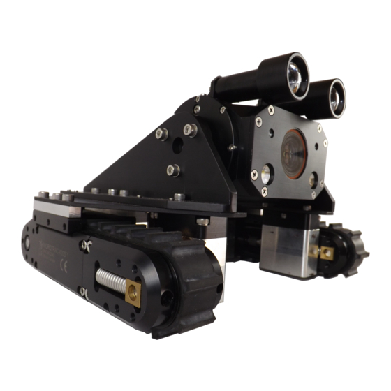
- Page 1 Eddyfi Robotics Inc 2569 Kenworth Road, Suite C Nanaimo, BC, V9T 3M4 CANADA +1.250.729.8080 info@eddyfitechnologies.com www.eddyfitechnologies.com Magg™ 310 MAGNETIC INSPECTION CRAWLER...
-
Page 2: Table Of Contents
Magg™ 310 Table of Contents About This Manual ............................4 System Description ............................4 Specifications ............................5 Precautions ............................... 6 Certification ............................... 6 Vehicle Overview ............................6 Dimensions ............................... 7 Safety ................................ 8 Intended Use ............................10 Laser Lines ............................. 11 System Setup .............................. - Page 3 Magg™ 310 Pre-Operations Check ..........................22 Post-Operations Check ........................... 23 ICON™ Software ............................ 24 Driving the Vehicle ..........................24 Maintenance ..............................24 Galvanic Corrosion Control ........................24 Rinsing and Cleaning ..........................25 Fuse Replacement ..........................25 Microtrac™ Maintenance ........................26 Tether Re-termination ..........................
-
Page 4: About This Manual
Furthermore, schematics or pictorials and detailed functionality may differ slightly from what is described in this manual. Eddyfi Technologies reserves the right to change and/or amend these specifications at any time without notice. Information in this manual does not necessarily replace specific regulations, codes, standards, or requirements of others such as government regulations. -
Page 5: Specifications
Magg™ 310 Specifications Min Vehicle Dimensions 194 x 286 x 280 mm (7.6 x 11.3 x 11 in) Vehicle Weight 6.2 kg (14 lb) Depth Rating 60 m (200 ft) Min Driving Surface Radius 1.5 m (60 in) Maximum Tether Length 100 m (330 ft) Tracks 2x Microtracs™... -
Page 6: Precautions
Magg™ 310 Precautions IMPORTANT: When configuring a 70V system, check to see if the tracks are compatible. Older versions of 4000 series Microtracs™ are not 70V compatible. Look for the Wide Input Voltage symbol \V/ located on the side plate of the track indicating 70V compatibility. Certification This system is built in accordance with the Low Voltage Directive 2006/95/EC and Directive 2014/35/EU, Machinery Directive 2006/42/EC, and Electromagnetic Compatibility Directive 2004/108/EC and Directive... -
Page 7: Dimensions
Magg™ 310 Dimensions Document: umed018307 Revision: A01 Created by: ST Date: 24 Feb 2021 IPN: 3097222-A01 Source Location: C:\epdm\isleng\products\ed-magghd\manuals\umed018307.docm Page 7 of 30... -
Page 8: Safety
WARNING: Hazardous Voltage 36-70 VDC. If the equipment is powered from a source other than an Eddyfi Technologies provided controller, the power supplied to the product must have reinforced isolation from the mains with no reference to earth ground. - Page 9 Magg™ 310 Warning: Avoid Magnetic Slamming. Extreme care must be taken when handling the vehicle, particularly when placing it onto a wall or into its storage box. Without taking heed of the sudden pull of the magnetic field onto a surface, the Magg™...
-
Page 10: Intended Use
Magg™ 310 WARNING: Trip Hazard - Never stand on the tether. A snap load to the tether may pull it out from underneath you and cause you to fall. Standing on the tether may also damage its internal conductors, cause unnecessary wear, and decrease its life. -
Page 11: Laser Lines
Magg™ 310 Laser Lines The Magg™ 310 is equipped standard with vertical laser lines (Class 2 lasers at 635 nm, 1.5 mW). Laser line separation is 70 mm (2.75 in). CAUTION: Class II Laser: Do not intentionally stare into the beam. -
Page 12: System Setup
Magg™ 310 System Setup Personnel Requirements Basic deployment of the Magg™ 310 system may be performed by one person. Operations at more complex worksites may require two people, especially when the console location is removed from the point of deployment. •... -
Page 13: System Power
Magg™ 310 System Power The Magg™ 310 is operated through an ICON™ Portable Controller, or a Rackmount Interface Box. These controllers provide power to the tether and vehicle. Refer to the Controller User Manual for further details and power requirements. If powering the system from a generator or inverter, refer to that unit’s operating manual for recommendations on continuous and peak load ratings. -
Page 14: Portable Reel Setup
Magg™ 310 Portable Reel Setup If your system includes a portable reel, follow these steps to operate: 1. Remove the shipping cap from the front of the case and insert the crank handle. 2. Connect the deck cable from the reel to the controller. 3. -
Page 15: Mini-Reel Setup
Magg™ 310 Mini-Reel Setup If your system includes a Mini-Reel, follow these steps to operate: 1. Remove the Mini-Reel from the shipping case. 2. Connect the deck cable from the reel to the Video Interface and Power Supply. 3. Connect the encoder deck cable from the reel to the Video Interface and Power Supply (if provided with Mini-Reel). -
Page 16: Tether Handling
Magg™ 310 Tether Handling The tether is one of the most important parts of the system. It feeds power and control signals to the system and returns data to the controller. If the tether is damaged from improper use, poor handling or an accident, the system may become inoperable. -
Page 17: Subconn Connector: Lubrication And Cleaning
Magg™ 310 SubConn Connector: Lubrication and Cleaning • Periodically apply Molykote 111 silicone grease or equivalent before mating connectors. • For dry mate connections, a layer of grease corresponding to 1/10 the socket depth should be applied to the female connector. •... -
Page 18: Vehicle Configuration
Magg™ 310 Vehicle Configuration Camera Mounting The Magg™ 310 camera can be mounted in a standard configuration or can be removed from the vehicle and mounted on an accessory pole. The camera can also be mounted in an alternate orientation option. Standard Mounting To install the camera onto the vehicle, do the following (removal is the reverse of installation): 1. -
Page 19: Pole Mounting
Magg™ 310 Pole Mounting Mounting the camera onto the optional inspection pole is nearly identical to the standard installation (see below). Alternate Mounting Mounting the camera onto the optional mount is as follows (removal is the reverse of installation): 1. Remove one magnet cup M5 x 30 mm SHCS from each side of the vehicle as shown below. 2. -
Page 20: Magnet Spacing
Magg™ 310 Magnet Spacing The Magg™ 310 vehicle comes equipped with magnet cups to enable the vehicle to maneuver on a vertical or inverted magnetically attractive surface. The magnet cups utilize rare earth permanent magnets and cannot be disabled (or turned off). The inspection surface must be carbon steel or alloy steel that has good magnetic properties. - Page 21 Magg™ 310 Magnet Spacing The Magg™ 310 vehicle comes with the tracks spaced down from the main chassis plate using four groups of 8mm and 4.5mm spacers (two groups per track). The vehicle comes with a kit of spacers to accommodate a wide range of track spacing.
-
Page 22: Fall Arrest
Magg™ 310 Fall Arrest IMPORTANT: A lifeline or fall arrest system should always be used when vehicle detachment from the working surface threatens injury to personnel or damage to equipment. A fall arrest system can be attached to the vehicle on either or both chassis handles. Additionally, one of the handles may be relocated using the two mounting holes located behind the camera. -
Page 23: Post-Operations Check
Magg™ 310 Visually inspect the vehicle and Microtracs™ to ensure that the moving parts are free of debris and functional. Make sure the track belt is free of debris and turns freely. Check the tether and vehicle whips for damage. ... -
Page 24: Icon™ Software
Do not mix anode types (zinc and aluminum) on the assembly, between vehicles or between structures. There must be only one anode type throughout. Magnesium anodes must never be used with Eddyfi Technologies equipment. -
Page 25: Rinsing And Cleaning
Magg™ 310 Rinsing and Cleaning After every mission check to see if the vehicle needs cleaning. 1. If the system has been used in salt water, thoroughly rinse the vehicle with fresh water prior to being stored away. Accelerated corrosion will result if the inspection system is not rinsed properly. Pay close attention to rinsing and cleaning the camera window, LED light dome and the spaces between moving parts and track belts. -
Page 26: Microtrac™ Maintenance
Microtrac™ Maintenance Refer to the Microtrac manual for Microtrac™ 4000 maintenance and servicing instructions. Tether Re-termination Tether termination is a specialized service beyond the scope of this manual. Contact Eddyfi Technologies if the tether is damaged or requires re-termination. Document: umed018307... -
Page 27: Troubleshooting
Magg™ 310 Troubleshooting Camera Control Problems 1. Not all the auxiliary lights are on. • The ICON™ software allows the lights to be controlled independently. Ensure all lights are enabled. Refer to the ICON interface manual. • Inspect for blown LEDs. 2. -
Page 28: Vehicle Issues
Magg™ 310 Vehicle Issues 1. Vehicle will not steer, or vehicle runs backward. • Tracks set to the wrong positions. • Track reverse setting incorrect in control software. • Node ID conflict between one or more devices on the vehicle. •... -
Page 29: Parts And Repairs
2569 Kenworth Road, Suite C Nanaimo, BC, V9T 3M4 CANADA TF 1.877.468.5886 T +1.250.729.8080 info@eddyfi.com www.eddyfitechnologies.com Eddyfi Technologies – US (American Authorized Distributor and Service Centre) 812 W 13th Street Deer Park, TX, 77536 T +1.281.542.3292 info@eddyfi.com www.eddyfitechnologies.com Warranty Repairs Warranty conditions are specified in the Warranty section. -
Page 30: Factory Returns To Canada
Warranty claims must return to the factory for evaluation. To return an item for evaluation or repair, first contact Eddyfi Technologies at our toll-free number or e- mail address. Eddyfi Technologies will supply a Return Merchandise Authorization (RMA) number with detailed shipping and customs instructions.
Need help?
Do you have a question about the Magg 310 and is the answer not in the manual?
Questions and answers