Eaton PowerXL DB1 Series Installation Manual
Variable frequency drives
Hide thumbs
Also See for PowerXL DB1 Series:
- Installation manual (96 pages) ,
- Parameter manual (46 pages) ,
- Installation manual (104 pages)

Related Manuals for Eaton PowerXL DB1 Series


Summary of Contents for Eaton PowerXL DB1 Series
- Page 1 Manual 11/20 MN040031EN PowerXL ™ Variable Frequency Drives Installation Manual L1 L2 (L) (N ) U V W...
- Page 2 No part of this manual may be reproduced, stored in a retrieval system, or transmit- ted in any form or by any means, electronic, mechanical, photocopying, micro-film- ing, recording, or otherwise, without the prior written permission of Eaton Industries GmbH, Bonn, Germany.
- Page 3 Danger! Dangerous electrical voltage! Before commencing the installation • Disconnect the power supply of the device. • Wherever faults in the automation system may cause damage to persons or property, external measures must • Ensure that devices cannot be accidentally retriggered. be implemented to ensure a safe operating state in the •...
-
Page 4: Table Of Contents
Replacement of the device fan for frame size FS1B....26 1.13.2 Replacement of the device fan for frame size FS2 ...... 29 1.14 Storage..................31 1.15 Charging the internal DC link capacitors ........32 1.16 Service and warranty..............32 DB1 Variable Frequency Drives 11/20 MN040031EN www.eaton.com... - Page 5 Grounding..................60 3.4.3 Shielding..................62 3.4.4 General installation diagram ............63 Electrical installation..............64 3.5.1 Connection to the power section..........65 3.5.2 Connection to control section ............68 3.5.3 Thermistor connection ..............73 DB1 Variable Frequency Drives 11/20 MN040031EN www.eaton.com...
- Page 6 5.2.5 DB1-32… device series..............96 5.2.6 DB1-34… device series..............97 Dimensions and frame size............98 Fuses.................... 99 Mains contactors................101 Mains chokes ................103 Brake resistors ................105 Accessories ................. 108 Index.................... 109 DB1 Variable Frequency Drives 11/20 MN040031EN www.eaton.com...
-
Page 7: About This Manual
0 About this manual 0.1 Target audience 0 About this manual This MN040031DE manual describes the DB1 Eaton variable frequency drives. Optional accessories When an external control unit is connected, the DB1 variable frequency drives require type DX-KEY-LED2 and DX-KEY-OLED with software update. -
Page 8: Change Protocol
Calculation of power loss P ✓ Installation dimensions, screws, ✓ Tightening torques for frame size FS2 Connection cross-section for frame size FS2 ✓ Cable cross-sections (technical data) ✓ Motor chokes ✓ 09/17 First edition DB1 variable frequency drive 11/20 MN040031DE Eaton.com... -
Page 9: Writing Conventions
→ All the specifications in this manual refer to the hardware and software versions documented in it. DB1 variable frequency drive 11/20 MN040031DE Eaton.com... -
Page 10: Documents With Additional Information
0.4 Documents with additional information → More information on the devices described here can be found on the internet at Eaton.eu/powerxl as well as in EATON Download Center: www.eaton.eu/documentation In the Quick Search box, enter the document name (“MN040031”, for example). 0.5 Abbreviations... -
Page 11: Mains Supply Voltages
-17.222 °C (T × 9/5 + 32 Speed revolutions per minute 1 rpm 1 min Weight pound 1 lb 0.4536 kg 2.205 Flow rate cubic feed per minute 1 cfm 1.698 m /min 0.5889 DB1 variable frequency drive 11/20 MN040031DE Eaton.com... -
Page 12: Db1 Device Series
The extensive accessories additionally increase the flexibility in all areas of application. L1 L2 (L) (N ) U V W Figure 1: DB1 variable frequency drive, frame size FS1 DB1 variable frequency drive 11/20 MN040031EN Eaton.com... -
Page 13: System Overview
④ ② U V W ③ Figure 2: System overview a DB1… variable frequency drive b Mains choke DX-LN… c DX-COM-STICK3 communication module and accessories (e.g. DX-CBL-… connection cable) d DX-KEY-… keypad (external) DB1 variable frequency drive 11/20 MN040031EN Eaton.com... -
Page 14: Checking The Delivery
The packaging must contain the following parts: • 10x DB1 device series variable frequency drive units, • an instruction leaflet IL040044ZU 10 x Figure 3: Equipment supplied DB1 variable frequency drive 11/20 MN040031EN Eaton.com... -
Page 15: Rated Data
1.4 Rated data The device-specific rated data of the DB1 variable frequency drive are listed on the device’s rating plate. L1 L2 (L ) (N ) U V W Figure 4: Rating plate location DB1 variable frequency drive 11/20 MN040031EN Eaton.com... - Page 16 Date of manufacture: 7/25/2016 Max. Amb. 60 °C Maximum permissible ambient air temperature (60 °C) Variable frequency drives are electrical equipment. Read the manual (in this case MN040031EN) before making any electrical connec- tions and commissioning. DB1 variable frequency drive 11/20 MN040031EN Eaton.com...
-
Page 17: Type Code
1 = Single-phase mains connection / three-phase motor connec- 3 = Three-phase mains connection / three-phase motor connec- Series DB1 = variable frequency drive, basic, series 1 (D = drives, B = basic, 1 = series) Figure 5: Type code DB1 variable frequency drive 11/20 MN040031EN Eaton.com... -
Page 18: Features
230 V, 50 Hz 220 - 240 V, 60 Hz filter DB1-122D3FN-N2CC 0.37 ✓ – – DB1-124D3FN-N2CC 0.75 ✓ – – DB1-127D0FN-N2CC ✓ FS1B – – DB1-127D0FN-N2CC-PFC 7 0.75 ✓ FS1C – ✓ DB1 variable frequency drive 11/20 MN040031EN Eaton.com... -
Page 19: Db1-32
400 V, 50 Hz 440 - 480 V, 60 Hz filter DB1-342D2FN-N2CC 0.75 ✓ – – DB1-344D1FN-N2CC ✓ – – DB1-344D1FB-N2CC ✓ ✓ – DB1-345D8FB-N2CC ✓ ✓ – DB1-349D5FB-N2CC ✓ ✓ – DB1 variable frequency drive 11/20 MN040031EN Eaton.com... -
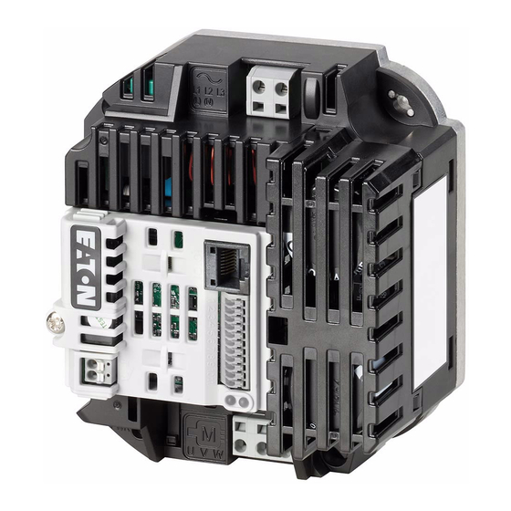
Page 20: Description
Fixing holes c Connection terminals in power section (motor feeder) d EMC screw e Control signal terminals f Protective earth conductor connector g Connection terminals for the relay contact h Communication interface (RJ45) DB1 variable frequency drive 11/20 MN040031EN Eaton.com... -
Page 21: Frame Size Fs1C
Fixing holes c Connection terminals in power section (motor feeder) d EMC screw e Control signal terminals f Protective earth conductor connector g Connection terminals for the relay contact h Communication interface (RJ45) DB1 variable frequency drive 11/20 MN040031EN Eaton.com... -
Page 22: Frame Size Fs2
EMC screw e Control signal terminals f Protective earth conductor connector g Connection terminals for the relay contact h Communication interface (RJ45) i Connection terminals in power section (brake chopper) j Fan DB1 variable frequency drive 11/20 MN040031EN Eaton.com... -
Page 23: Voltage Classes
Motor: 0.5 kW (230 V, 50 Hz), 1/4 HP (220 - 240 V, 60 Hz) Motor L1/L L2/N 230 V (U = 1 ~ 110 - 230 V) 3 ∼ EMC Filter Figure 10: DB1-1M… DB1 variable frequency drive 11/20 MN040031EN Eaton.com... - Page 24 Motor: 0.75 - 1.5 kW (400 V, 50 Hz), 1 - 2 HP (460 V, 60 Hz) Motor L1/L L2/N 400 V (U = 3 ~ 400 V) 3 ∼ 460 V (U = 3 ~ 480 V) EMC Filter Brake Chopper (FS2) Figure 13: DB1-34… DB1 variable frequency drive 11/20 MN040031EN Eaton.com...
-
Page 25: Selection Criteria
60 °C. Appropriate cooling must be taken into account during configuration (→ section 3.3.2, “Cooling measures”, page 52). The lower the ambient temperature, the more favorable the cooling ratios. DB1 variable frequency drive 11/20 MN040031EN Eaton.com... -
Page 26: Performance Reduction (Derating)
1000 m during operation. Derating for the set-up altitude Permissible set-up altitude Reduction by without with Derating Derating 1,000 m up to 2,000 m 1 % per 100 m above 1,000 m DB1 variable frequency drive 11/20 MN040031EN Eaton.com... -
Page 27: Proper Use
→ Always observe the technical data and connection conditions! For additional information, refer to the equipment nameplate or label at the variable frequency drive and the documentation. Any other usage constitutes improper use. DB1 variable frequency drive 11/20 MN040031EN Eaton.com... -
Page 28: Maintenance And Inspection
If the DB1 variable frequency drive is damaged by external influences, repair is not possible. Dispose of the device according to the applicable environmental laws and provisions for the disposal of electrical or electronic devices. DB1 variable frequency drive 11/20 MN040031EN Eaton.com... -
Page 29: Replacement Of The Device Fan
FS1B and FS2. 1.13.1 Replacement of the device fan for frame size FS1B Remove the old device fan Figure 15: Remove the control board Figure 16: Remove the fan cover DB1 variable frequency drive 11/20 MN040031EN Eaton.com... - Page 30 1 DB1 device series 1.13 Replacement of the device fan Figure 17: Remove the old fan Installation of the new fan Figure 18: Install the new fan DB1 variable frequency drive 11/20 MN040031EN Eaton.com...
- Page 31 1 DB1 device series 1.13 Replacement of the device fan Figure 19: Put on the fan cover Figure 20: Put on the control board DB1 variable frequency drive 11/20 MN040031EN Eaton.com...
-
Page 32: Replacement Of The Device Fan For Frame Size Fs2
The fan is plugged in and can be removed from the top of the device. The following illustrations show the procedure for replacement. Figure 21: Remove the control board Figure 22: Remove the old fan DB1 variable frequency drive 11/20 MN040031EN Eaton.com... - Page 33 1 DB1 device series 1.13 Replacement of the device fan Figure 23: Install the new fan Figure 24: Put on the control board DB1 variable frequency drive 11/20 MN040031EN Eaton.com...
-
Page 34: Storage
To prevent damage to the variable frequency drive’s internal DC link capacitors, it is not recommended that the variable frequency drive is not stored for more than 12 months (→ section 1.15, “Charging the internal DC link capacitors”). DB1 variable frequency drive 11/20 MN040031EN Eaton.com... -
Page 35: Charging The Internal Dc Link Capacitors
If some of the information printed on the rating plate is not legible, please state only the data which are clearly legible. Information concerning the warranty can be found in the Eaton Industries GmbH Terms and Conditions. Break-Down Service Please contact your local representative: www.eaton.eu/aftersales... -
Page 36: Engineering
All applicable laws and local standards must be complied with when planning and carrying out the installation. Not following the recommendations provi- ded may result in problems that will not be covered by the warranty. DB1 variable frequency drive 11/20 MN040031EN Eaton.com... - Page 37 (temperature, speed) g Load system: Driven system equipment (process, speed, torque) ⑥ ϑ ⑦ M, n Figure 25: Magnet system example (overall system as its own system or as part of a larger system) DB1 variable frequency drive 11/20 MN040031EN Eaton.com...
-
Page 38: Electrical Power Network
EMC- and Low Voltage Directives. Good grounding measures are a prerequisite for the effective use of further measures such as shielding or filters. Without respective grounding measures, further steps are superfluous. DB1 variable frequency drive 11/20 MN040031EN Eaton.com... -
Page 39: Mains Voltage And Frequency
→ The mains chokes assigned to the DB1 variable frequency dri- ves can be found in → section 2.5, “Mains chokes”, page 41. DB1 variable frequency drive 11/20 MN040031EN Eaton.com... -
Page 40: Total Harmonic Distortion (Thd)
(harmonics), parallel resonances and undefined conditions can occur. In the project planning for the connection of variable frequency drives to AC supply systems with undefined circumstances, consider using mains chokes. DB1 variable frequency drive 11/20 MN040031EN Eaton.com... -
Page 41: Cable Cross-Sections
(EN 60947-3) • A circuit-breaker designed to disconnect the circuit as per EN 60947-2 In all other regions, the applicable national and local safety regulations must be complied with. DB1 variable frequency drive 11/20 MN040031EN Eaton.com... -
Page 42: Fuses
Other protective measures against direct and indirect contact can be used for DB1 variable frequency drives, including isolating them from the supply sys- tem with the use of a transformer. DB1 variable frequency drive 11/20 MN040031EN Eaton.com... -
Page 43: Mains Contactors
1.25 times higher input current. → For the rated mains contactors for DB1 variable frequency drives, please refer to → section 5.5, “Mains contactors”, page 101. DB1 variable frequency drive 11/20 MN040031EN Eaton.com... -
Page 44: Mains Chokes
96 % of the mains voltage U → For the rated mains chokes for DB1 variable frequency drives, please refer to → section 5.6, “Mains chokes”, page 103. DB1 variable frequency drive 11/20 MN040031EN Eaton.com... -
Page 45: Radio Interference Suppression Filter
In the case of power drive systems (PDS) with variable fre- quency drives, electromagnetic compatibility (EMC) measures must already be taken into account during the engineering stage, as making changes during assembly and installation and retroactively fixing things will be more expensive. DB1 variable frequency drive 11/20 MN040031EN Eaton.com... -
Page 46: Brake Resistors
DC link voltage to increase to the switch-on vol- tage’s magnitude. Device type Mains connec- Voltage class Brake chopper Brake chopper tion DB1-344D1FB-N2CC 3-phase 400 V 780 V 756 V DB1-34508FB-N2CC DB1-349D5FB-N2CC DB1 variable frequency drive 11/20 MN040031EN Eaton.com... -
Page 47: Switch-Disconnectors
EN 60204. Eaton T0…/MSB/…, P1…/MSB/…, and P3…/MSB/… enclosed switch-dis- connectors are designed for local installation with an IP65 degree of protec- tion. -
Page 48: Three-Phase Motors
(in order to ensure that the motor will be protected). • When running tests or commissioning a system with significantly lower motor outputs, the motor’s rated operational current must be adjusted using parameter P-08 (“rated motor current”). DB1 variable frequency drive 11/20 MN040031EN Eaton.com... -
Page 49: Circuit Types With Three-Phase Motors
Mains voltage: 1 ~ 230 V; Output voltage: 3 ~ 230 V → DB1-124D3… Motor connection DB1 variable as per as per frequency drive U1 (-U2) T1 (-T4) V1 (-V2) T2 (-T5) W1 (-W2) T3 (-T6) DB1 variable frequency drive 11/20 MN040031EN Eaton.com... -
Page 50: Permanent Magnet Motor (Pm Motor)
The control response for BLDC motors is to a large extent the same as that for a shunt DC motor. BLDC motors are primarily used in drive systems for machine tools, servo drives in conveyor systems, and compressors and metering pumps. DB1 variable frequency drive 11/20 MN040031EN Eaton.com... -
Page 51: Synchronous Reluctance Motor (Syncrm)
Change the value for P-61 to 1 (“Motor identification”). Automatic autotune to determine the motor parameters when the motor is stationary. • P-62 (“MSC gain”): Adjust the gain factor for the speed controller. DB1 variable frequency drive 11/20 MN040031EN Eaton.com... -
Page 52: Connecting Ex Motors
Temperature sensors in the motor windings (thermistor, Thermo-Click) must not be connected directly to the variable frequency drive, but instead must be connected through a relay approved for the Ex area (e.g. EMT6). DB1 variable frequency drive 11/20 MN040031EN Eaton.com... -
Page 53: Installation
Environments with mechanical vibration and impact loads that go beyond the requirements in EN 61800-5-1. • Areas in which the variable frequency drive takes care of safety functions required to guarantee machine and personnel protection. DB1 variable frequency drive 11/20 MN040031EN Eaton.com... -
Page 54: Assembly
In doing so, you must ensure that the cooling system used in the installation position is capable of removing lost heat without this causing the permitted temperature on the variable frequency drive cooling surface to be exceeded. DB1 variable frequency drive 11/20 MN040031EN Eaton.com... -
Page 55: Cooling Measures
Automatic switching of the switching frequency from 12 kHz to 8 kHz 94 °C Shutdown due to over-temperature when P-17 ≧ 8 kHZ 97 °C Shutdown due to over-temperature when P-17 = 4 kHZ DB1 variable frequency drive 11/20 MN040031EN Eaton.com... - Page 56 During installation, it is important to ensure that the cooling air can circulate adequately and that there are no hotspots. DB1 variable frequency drive 11/20 MN040031EN Eaton.com...
- Page 57 96.00 95.90 95.90 95.70 95.70 95.60 DB1-124D3FN-N2CC 96.00 95.90 95.90 95.70 95.70 95.60 DB1-127D0FN-N2CC 95.00 94.70 94.40 0.3. 94.10 93.40 DB1-127D0FN-N2CC-PFC 0.42 95.00 0.36 94.70 0.30 94.40 0.25 94.10 0.20 93.40 0.14 92.00 DB1 variable frequency drive 11/20 MN040031EN Eaton.com...
- Page 58 0.30 94.70 0.29 94.40 0.27 94.10 0.20 93.40 DB1-342D2FN-N2CC 97.70 97.30 96.80 97.00 96.50 96.00 DB1-344D1FN-N2CC 97.70 97.30 96.80 97.00 96.50 96.00 DB1-344D1FB-N2CC 0.64 97.60 0.49 97.20 0.37 96.80 0.28 96.40 0.18 95.40 DB1 variable frequency drive 11/20 MN040031EN Eaton.com...
- Page 59 °C K / W DB1-345D8FN-N2CC 0.64 97.60 0.49 97.20 0.37 96.80 0.28 96.40 0.18 95.40 DB1-349D5FN-N2CC 0.33 97.30 0.26 96.90 96.50 0.15 96.00 94.90 DB1 variable frequency drive 11/20 MN040031EN Eaton.com...
-
Page 60: Mounting
Table 10: Installation dimensions, screws, tightening torques Frame size Screw Tightening torque Numbe Size lb-in FS1, FS1B 3.74 3.90 M4x20 35.4 FS1C 107.5 4.23 6.22 M4x20 35.4 4.92 6.26 M4x20 35.4 DB1 variable frequency drive 11/20 MN040031EN Eaton.com... -
Page 61: Correct Emc Installation
Ground all conductive components and housings in a drive system using as short a line as possible with the greatest possible cross-section (Cu braid). WARNING In a home environment this product can cause high-frequency interference, which may require remedial action. DB1 variable frequency drive 11/20 MN040031EN Eaton.com... -
Page 62: Emc Measures In The Control Panel
→ Never lay control or signal cables ② in the same duct as power cables ①. Analog signal cables (measured values, set points, and correc- tion values) must be routed inside shielded conduits. DB1 variable frequency drive 11/20 MN040031EN Eaton.com... -
Page 63: Grounding
(beam, ceiling joist), a ground electrode in the ground, or a mains ground bus. The ground points must meet the requirements set forth by the applicable national and local industrial safety regulations and/or regulations for electrical systems. DB1 variable frequency drive 11/20 MN040031EN Eaton.com... - Page 64 IT networks must be suitable for operation with power electronic devices (IEC 61557-8). → The location of the EMC screw in the respective frame size can be found in → section 1.7, “Description”. DB1 variable frequency drive 11/20 MN040031EN Eaton.com...
-
Page 65: Shielding
(depending on the EMC environment). → Control and signal lines (analog, digital) should always be groun- ded on one end, in the immediate vicinity of the supply voltage source (PES). DB1 variable frequency drive 11/20 MN040031EN Eaton.com... -
Page 66: General Installation Diagram
Cable routing: Do not route power cables and control cables parallel to each other in the same cable duct. If they need to be routed in parallel, they should be in separate metal cable ducts (in order to meet EMC requirements). DB1 variable frequency drive 11/20 MN040031EN Eaton.com... -
Page 67: Electrical Installation
(5) minutes after the supply voltage has been switched off (internal DC link capacitor discharging time). Pay attention to hazard warnings! → Complete the following steps with the specified tools and without using force. DB1 variable frequency drive 11/20 MN040031EN Eaton.com... -
Page 68: Connection To The Power Section
The number and the arrangement of the connection terminals used depend on the variable frequency drive’s size and model. WARNING The variable frequency drive must always be connected with ground potential via a grounding conductor (PE). DB1 variable frequency drive 11/20 MN040031EN Eaton.com... - Page 69 0.08 - 2.5 28 - 12 0.25 - 1.5 10 - 12 0.39 - 0.47 0.2 - 6 24 - 10 0.2 - 6 24 - 10 0.25 - 2.5 n/a = not allowed DB1 variable frequency drive 11/20 MN040031EN Eaton.com...
- Page 70 PE terminals, minimizing the loads on the cable screen (high equalizing currents). The following figure shows the construction of a four-wire, shielded motor cable (recommended specifications). DB1 variable frequency drive 11/20 MN040031EN Eaton.com...
-
Page 71: Connection To Control Section
When using more than one control voltage, we recommend using separate cables. Example 24 V DC at control signal terminals 1, 2, 3, 4, 6, and 8 and 110 V AC or 230 V AC at the relay contact. DB1 variable frequency drive 11/20 MN040031EN Eaton.com... - Page 72 • analog: 0 - +10 V, maximum 20 mA switchable using parameter P-25 Reference potential 0 V = connection terminal 7 – Modbus+ Modbus- Relay output RO1 Potential-free N/O contact 250 V/6A AC1 30 V/5A DC1 DB1 variable frequency drive 11/20 MN040031EN Eaton.com...
- Page 73 0 - f (P-01) The control cables should be shielded and twisted for the external connec- tion. The screening is applied on one side in the proximity of the variable frequency drive (PES). DB1 variable frequency drive 11/20 MN040031EN Eaton.com...
- Page 74 We recommend connecting the loads connected to the relay contact as follows: 250 V ∼ : ≦ 6 A 30 V ⎓ : ≦ 5 A Varistor RC filter Diode Figure 41: Connection examples with suppressor circuit DB1 variable frequency drive 11/20 MN040031EN Eaton.com...
- Page 75 MN040018: “Modbus RTU – Communication manual for DA1, DC1, DE1 variable frequency drives” • MN040019: “CANopen – communication manual for DA1, DC1, DE11 variable frequency drives” → DB1 variable frequency drives have no internal bus termination resistor. UseEASY-NT-R as needed. DB1 variable frequency drive 11/20 MN040031EN Eaton.com...
-
Page 76: Thermistor Connection
The thermistors and temperature switches used must be PTC-type units (PTC characteristic, positive temperature coefficient). These are triggered as a resistance value of approx. 2.5 kΩ - 3 kΩ, and a reset is triggered at approx.1.9 kΩ - 1 kΩ. DB1 variable frequency drive 11/20 MN040031EN Eaton.com... -
Page 77: Block Diagrams
: three-phase, 230 V, 0 - 50/60 Hz (max. 500 Hz) 1 AC 110 - 115 V 50/60 Hz L1/L L2/N RS485 Modbus RTU Modbus CANopen OP-Bus 3 AC 230 V Figure 44: Block diagram DB1-1D… DB1 variable frequency drive 11/20 MN040031EN Eaton.com... -
Page 78: Db1-1M
: three-phase, 230 V, 0 - 50/60 Hz (max. 500 Hz) 1 AC 110 - 230 V 50/60 Hz L1/L L2/N RS485 Modbus RTU Modbus CANopen OP-Bus 3 AC 230 V Figure 45: Block diagram DB1-1M… DB1 variable frequency drive 11/20 MN040031EN Eaton.com... -
Page 79: Db1-12
3 AC 230 V Figure 46: Block diagram DB1-12… Variable frequency drive with single-phase mains connection and three-phase motor connection ① Devices with frame size FS2 allow the connection of brake resistors (DC+, BR). DB1 variable frequency drive 11/20 MN040031EN Eaton.com... -
Page 80: Db1-127D0Fn-N2Cc-Pfc
, 0 - 50/60 Hz (max. 500 Hz) 1 AC 200 - 240 V 50/60 Hz L1/L L2/N RS485 Modbus RTU Modbus CANopen OP-Bus 3 AC 230 V Figure 47: Block diagram DB1-127D0FN-N2CC-PFC DB1 variable frequency drive 11/20 MN040031EN Eaton.com... -
Page 81: Db1-32
: three-phase, 230 V, 0 - 50/60 Hz (max. 500 Hz) 1 AC 200 - 240 V 50/60 Hz L1/L L2/N RS485 Modbus RTU Modbus CANopen OP-Bus 3 AC 230 V Figure 48: Block diagram DB1-32… DB1 variable frequency drive 11/20 MN040031EN Eaton.com... -
Page 82: Db1-34
3 AC 230/400/460 V Figure 49: Block diagram DB1-34… Variable frequency drive with three-phase mains connection and three-phase motor connection ① Devices with frame size FS2 allow the connection of brake resistors (DC+, BR). DB1 variable frequency drive 11/20 MN040031EN Eaton.com... -
Page 83: Insulation Testing
1000 V. The insulation resistance must be greater than 1 MΩ. → Take the instructions from the motor manufacturer into account when testing the insulation resistance. DB1 variable frequency drive 11/20 MN040031EN Eaton.com... -
Page 84: Protection Against Electric Shock
Table 41.1 or otherwise within 5 seconds – whichever applies - in accordance with IEC/HD 60364-41 (DIN VDE 0100-410; VDE 0100-410):2007-06). DB1 variable frequency drive 11/20 MN040031EN Eaton.com... -
Page 85: Operation
(→ MN040034EN). The direction of action of a coupled machine will allow the motor to start. All EMERGENCY STOP and protection functions are in the proper state. DB1 variable frequency drive 11/20 MN040031EN Eaton.com... -
Page 86: Operational Warnings
DANGER Following a shutdown (fault, mains voltage off), the motor may start automatically (when the mains voltage is switched back on) if the automatic restart function has been enabled (→ parameters P-31). DB1 variable frequency drive 11/20 MN040031EN Eaton.com... - Page 87 If motors are to be operated with frequencies higher than the standard 50 or 60 Hz, then these operating ranges must be approved by the motor manufacturer. Otherwise the motors could be damaged. DB1 variable frequency drive 11/20 MN040031EN Eaton.com...
-
Page 88: Commissioning (Default Setting)
(L1/L, L2/N, L3), the switching power supply unit will generate the control voltage in the DC link voltage. At this point, the variable frequency drive will be ready for operation (correct operating status) and in Stop mode. DB1 variable frequency drive 11/20 MN040031EN Eaton.com... - Page 89 P-24. +24 V STOP P-07 = 50 Hz ① P-03 = 5 s Figure 50: Start-stop command at maximum set point voltage, acceleration ramp 5 s DB1 variable frequency drive 11/20 MN040031EN Eaton.com...
-
Page 90: Technical Data
Fast transient burst (EFT/B, EN 61000-4-4: 2004) ±1, at 5 kHz, control signal terminal ±2, at 5 kHz, motor connection terminals, Single-phase mains connection terminals ±2, at 5 kHz, three-phase mains connection terminals DB1 variable frequency drive 11/20 MN040031EN Eaton.com... - Page 91 Maximum short-circuit current (supply voltage) SCCR Mains switch-on frequency Maximum of one time every 30 seconds Mains network configuration (AC power supply TN and TT network with directly grounded star point network) Inrush current < I DB1 variable frequency drive 11/20 MN040031EN Eaton.com...
- Page 92 20 - 100 % of torque load range) Response time (enable IGBT) < 10 DC braking Time before start 0 - 25, in the event of a stop Motor pick-up control function all frame sizes DB1 variable frequency drive 11/20 MN040031EN Eaton.com...
- Page 93 Accuracy < 1 to the end value Interface (RJ45) OP bus, Modbus RTU, CANopen, RS485 Response time (after valid command) < 8 (Modbus, CANopen) < 8 (OP bus: Master slave, 60 ms cycle) DB1 variable frequency drive 11/20 MN040031EN Eaton.com...
-
Page 94: Specific Rated Data
DB1 device series (12 = single-phase mains connection, 230 V) D B1 - 3 4 4D1 … Rated current (4D1 ≙ 4.1 A) DB1 device series (34 = three-phase mains connection, 400 V) DB1 variable frequency drive 11/20 MN040031EN Eaton.com... -
Page 95: Db1-1D
50 / 25 @ 8 kHz 0 / 100 @ 8 kHz 0 / 50 @ 8 kHz 0 / 25 @ 8 kHz in no-load state, (device not enabled) Frame size – – FS1B DB1 variable frequency drive 11/20 MN040031EN Eaton.com... -
Page 96: Db1-1M
0 / 100 @ 8 kHz 0 / 50 @ 8 kHz 0 / 25 @ 8 kHz in no-load state, (device not enabled) Frame size – – FS1C Note: n/ s = not specified DB1 variable frequency drive 11/20 MN040031EN Eaton.com... -
Page 97: Db1-12
0 / 100 @ 8 kHz 0 / 50 @ 8 kHz 0 / 25 @ 8 kHz in no-load state, (device not enabled) Frame size – – FS1C Note: n/ s = not specified DB1 variable frequency drive 11/20 MN040031EN Eaton.com... -
Page 98: Db1-12
0 / 100 @ 8 kHz 0 / 50 @ 8 kHz 0 / 25 @ 8 kHz in no-load state, (device not enabled) Frame size – – FS1B Note: n/ s = not specified DB1 variable frequency drive 11/20 MN040031EN Eaton.com... -
Page 99: Db1-32
0 / 100 @ 8 kHz 0 / 50 @ 8 kHz 0 / 25 @ 8 kHz in no-load state, (device not enabled) Frame size – – FS1B Note: n/ s = not specified DB1 variable frequency drive 11/20 MN040031EN Eaton.com... -
Page 100: Db1-34
0 / 100 @ 8 kHz 0 / 50 @ 8 kHz 0 / 25 @ 8 kHz – in no-load state, (device not enabled) P Frame size Note: n/ s = not specified DB1 variable frequency drive 11/20 MN040031EN Eaton.com... -
Page 101: Dimensions And Frame Size
(4.23) (0.61) (7.32) (6.22) (0.55) (3.19) (0.2) (0.22) (3.09) 12.4 1.15 (5.67) (4.92) (0.49) (7.6) (6.26) (0.67) (3.54) (0.34) (0.28) (2.5) 1 in = 1’’ = 25.4 mm, 1 mm = 0.0394 in DB1 variable frequency drive 11/20 MN040031EN Eaton.com... -
Page 102: Fuses
5 Technical data 5.4 Fuses 5.4 Fuses The Eaton circuit-breakers and fuses listed below are examples and can be used without additional measures. If you use other circuit-breakers and fuses, make sure to take their protective characteristics and operational voltage into account. When using other cir- cuit-breakers, it may be necessary to also use fuses depending on the circuit- breaker's model, design, and settings. - Page 103 ④ DB1-342D2… FAZ-B6/3 PKM0-6.3 6D27 LPJ-6SP DB1-344D1… FAZ-B10/3 PKM0-10 10D27 LPJ-10SP DB1-345D8… FAZ-B10/3 PKM0-10 10D27 LPJ-10SP DB1-349D5… 10.7 FAZ-B16/3 PKM0-16 16D27 LPJ-15SP 1) Maximum short-circuit current of the supply network: 100 kA RMS DB1 variable frequency drive 11/20 MN040031EN Eaton.com...
-
Page 104: Mains Contactors
WARNING Inching operation is not permissible via the mains contactor. (Pause time ≧ 30 s between switching off and on). P1DILEM DILEM P1DILEM Figure 52: Mains contactor at single-phase connection (DB1-12…) DB1 variable frequency drive 11/20 MN040031EN Eaton.com... - Page 105 : 380 (-10 %) - 480 (+10 %) V : 400 V AC, three-phase / U : 400 V AC, three-phase DB1-342D2… DILEM-… DILEM-… DB1-344D1… DILEM-… DILEM-… DB1-345D8… DILEM-… DILEM-… DB1-349D5… 10.7 DILEM-… DILEM-… DB1 variable frequency drive 11/20 MN040031EN Eaton.com...
-
Page 106: Mains Chokes
: 200 (-10 %) - 240 (+10 %) V : 230 V AC, single-phase / U : 230 V AC, three-phase DB1-122D3… DX-LN1-006 DX-LN1-006 DB1-124D3… DX-LN1-013 11.7 DX-LN1-013 DB1-127D0… 15.5 DX-LN1-018 16.4 DX-LN1-018 DB1-127D0FN-N2CC-PFC DX-LN1-013 11.7 DX-LN1-009 DB1 variable frequency drive 11/20 MN040031EN Eaton.com... - Page 107 : 380 (-10 %) - 480 (+10 %) V : 400 V AC, three-phase / U : 400 V AC, three-phase DB1-342D2… DX-LN3-004 DX-LN3-004 DB1-344D1… DX-LN3-006 DX-LN3-006 DB1-345D8… DX-LN3-010 DX-LN3-010 DB1-349D5… 10.7 DX-LN3-016 15.2 DX-LN3-016 DB1 variable frequency drive 11/20 MN040031EN Eaton.com...
-
Page 108: Brake Resistors
(centrifugal pumps, fans). • High duty: high load with long braking duration and high duty factor (at least 30 %), e.g. for elevators, downhill conveyors, winders, centrifu- ges, flywheel motors, and large fans. DB1 variable frequency drive 11/20 MN040031EN Eaton.com... - Page 109 → For more information and technical data on the DX-BR… series brake resistors listed here, please refer to the corresponding installation leaflet for the individual models: IL04012024Z, IL04011ZU, IL04014ZU, IL04015ZU and IL04021ZU. DB1 variable frequency drive 11/20 MN040031EN Eaton.com...
- Page 110 5 Technical data 5.7 Brake resistors DB1 variable frequency drive 11/20 MN040031EN www.eaton.com...
-
Page 111: Accessories
DX-SPL-RJ45-3SL RJ45, 8-pin, splitter, 3 sockets lL04012023Z drivesConnect PC parameter configuration software for variable frequency MN040003 drive with integrated oscilloscope function AP = Application Note MN = Manual IL = Instruction Leaflet DB1 variable frequency drive 11/20 MN040031EN Eaton.com... -
Page 112: Index
......98 Disconnecting device ..... . 38 DB1 Variable Frequency Drives 11/20 MN040031EN www.eaton.com... - Page 113 ....... . 14 DB1 Variable Frequency Drives 11/20 MN040031EN www.eaton.com...
- Page 114 ........98 DB1 Variable Frequency Drives 11/20 MN040031EN www.eaton.com...
Need help?
Do you have a question about the PowerXL DB1 Series and is the answer not in the manual?
Questions and answers