
Subscribe to Our Youtube Channel
Related Manuals for Tektronix CT-1

Summary of Contents for Tektronix CT-1
- Page 1 (217) 352-9330 | Click HERE Find the Tektronix TCA-BNC at our website:...
- Page 2 CT-1 and CT-2 Current Transformer Instructions *P070795702* 070-7957-02...
- Page 4 CT-1 and CT-2 Current Transformer Instructions www.tektronix.com 070-7957-02...
- Page 5 Copyright © Tektronix. All rights reserved. Licensed software products are owned by Tektronix or its subsidiaries or suppliers, and are protected by national copyright laws and international treaty provisions. Tektronix products are covered by U.S. and foreign patents, issued and pending. Information in this publication supersedes that in all previously published material.
- Page 6 Tektronix, with shipping charges prepaid. Tektronix shall pay for the return of the product to Customer if the shipment is to a location within the country in which the Tektronix service center is located. Customer shall be responsible for paying all shipping charges, duties, taxes, and any other charges for products returned to any other locations.
-
Page 8: Table Of Contents
General Safety Summary ..................Compliance Information ..................Safety Compliance.................... Environmental Considerations ................Introduction ......................Description ......................Operation ......................Installing the CT-1 or CT-2 ................... Injecting Current Signals..................Low Frequency Response..................Probe Handling....................Specifications ....................... Replaceable Parts List..................... Parts Ordering Information .................. -
Page 9: General Safety Summary
Avoid Exposed Circuitry. Do not touch exposed connections and components when power is present. Do Not Operate in Wet/Damp Conditions. Do Not Operate in an Explosive Atmosphere. Keep Product Surfaces Clean and Dry. CT-1 and CT-2 Current Transformer Instructions... - Page 10 DANGER indicates an injury hazard immediately accessible as you read the marking. WARNING indicates an injury hazard not immediately accessible as you read the marking. CAUTION indicates a hazard to property including the product. The following symbol(s) may appear on the product: CT-1 and CT-2 Current Transformer Instructions...
-
Page 11: Compliance Information
Pollution Degree 4. Pollution that generates persistent conductivity through conductive dust, rain, or snow. Typical outdoor locations. Pollution Degree Pollution Degree 2 (as defined in IEC 61010-1). Note: Rated for indoor use only. CT-1 and CT-2 Current Transformer Instructions... -
Page 12: Environmental Considerations
Support/Service section of the Tektronix Web site (www.tektronix.com). Restriction of Hazardous This product has been classified as Monitoring and Control equipment, and is outside the scope of the 2002/95/EC RoHS Directive. Substances CT-1 and CT-2 Current Transformer Instructions... - Page 13 Compliance Information CT-1 and CT-2 Current Transformer Instructions...
-
Page 14: Introduction
WARNING. To avoid electric shock, do not exceed the bare wire voltage ratings (30 VAC or 42 Vpk). Depending on which instrument the CT-1 or CT-2 is connected to, the exposed current transformer case metal may be floating (elevated above earth potential). Whenever possible, connect the mounting stud to earth ground. -
Page 15: Description
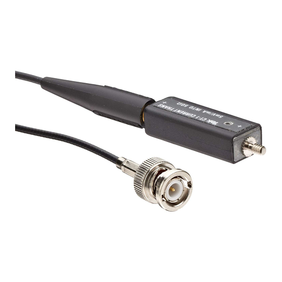
For each mA of input current the signal terminal develops 5 mV (CT-1) or 1 mV (CT-2) when properly terminated into 50 Ω. The sensitivity of the CT-1 is 5 mV/mA (200 μA/mV) and the CT-2 is 1 mV/mA (1 mA/mV) when properly terminated into 50 Ω. - Page 16 (preferred connection). Figure 3: CT-2 frequency response vs. DC current The CT-1 and CT-2 consist of a current transformer and a flexible probe cable that attaches between the transformer and the oscilloscope. In addition, the CT-1 and CT-2 have an internal termination resistor that reduces reflections that allows the transformer to be disconnected from the probe cable and left in the circuit.
-
Page 17: Operation
(see recommended accessories in the Replaceable Parts List). The following figure shows the output of the CT-1 compared with the input pulse from a 250 ps fast-rise pulse generator and the output of the CT-2 as seen by a 100 MHz oscilloscope system. -
Page 18: Injecting Current Signals
Operation If the CT-1 or CT-2 is connected so that the positive (+) label side faces the signal source, the input current and output voltage are in phase. This is the preferred connection. For pulses with a risetime slower than 1 ns, the CT-1 or CT-2 may be connected in either polarity. -
Page 19: Low Frequency Response
To generate larger secondary signals, pass the wire through the transformer core multiple times. To calculate how much voltage to apply to the CT-1 probe to inject a desired amount of current, multiply the desired current to be injected by 5. For the CT-2 the voltage to apply is equivalent to the desired current. -
Page 20: Probe Handling
Tektronix for replacement. CAUTION. Dropping the CT-1 or CT-2 transformer may break the probe. Do not pull or stretch the P6041 cable or place objects on the cable. This may damage the probe cable. - Page 21 Operation CT-1 and CT-2 Current Transformer Instructions...
-
Page 22: Specifications
Specifications The following table lists the electrical characteristics of the CT-1 and CT-2 Transformers when they are connected to the P6041 Probe cable. Table 1: Electrical characteristics Specification CT-1 with P6041 Probe CT-2 with P6041 Probe Sensitivity 5 mV/mA, ±3% into a 50 Ω load 1 mV/mA, ±3% into a 50 Ω... - Page 23 Specifications Table 2: General specifications (CT-1 and CT-2) Environmental Temperature Operating: –10 °C to +55 °C (+14 °F to +131 °F) Nonoperating: -51 °C to +71 °C (-60 °F to +160 °F) Humidity Operating: 5% to 95% RH (relative humidity) at up to +30 °C (+86 °F), 5% to 60% RH above +30 °C (+86 °F) up to +55 °C (+131 °F), non-condensing...
-
Page 24: Replaceable Parts List
Replaceable Parts List Replaceable Parts List This section contains a list of the replaceable parts for the CT-1 and CT-2. Use this list to identify and order replacement parts. Parts Ordering Information Replacement parts are available through your local Tektronix field office or representative. -
Page 25: Replaceable Parts List
2100 EARLYWOOD DR PO BOX 547 80009 TEKTRONIX INC 14150 SW KARL BRAUN DR PO BOX 500 BEAVERTON, OR 97077-0001 29585 XEROX CORPORATION 14181 SW MILLIKAN WAY BEAVERTON, OR 97005 Figure 8: CT-1 and CT-2 accessories CT-1 and CT-2 Current Transformer Instructions... - Page 26 CURRENT TRANSFORMER:CT-1 OR CT-2 WITH CT-1 OR CT-2 P6041 (OPTION 09 W/O P6041) P6041 80009 P6041 103-0028-00 24931 28A100-2 ADAPTER,CONN:BNC,FEMALE TO FEMALE,1.3 L,GOLD/NICKEL 011-0049-01 TERMN,COAXIAL:50 OHM,2W,BNC 80009 011-0049-01 070-7957-XX MANUAL,TECH:CT1/CT2 PROBE,DP TK2548 PER TEK DOCUMENTATION CT-1 and CT-2 Current Transformer Instructions...
Need help?
Do you have a question about the CT-1 and is the answer not in the manual?
Questions and answers