Table of Contents
Advertisement
Quick Links
Technical Services 800-381-9312 | +1-401-781-8220
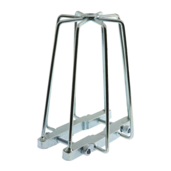
Model G5 Sprinkler Guards for
Use with Series DS-1 Sprinklers
Standard, Deep, and No Escutcheons
General
Description
The TYCO Model G5 Sprinkler Guards
are designed for use with Series DS-1
Sprinklers located in areas that make
the sprinklers susceptible to mechani-
cal or physical damage.
NOTICE
The Model G5 Sprinkler Guard can be
installed only on sprinklers with stan-
dard and deep escutcheons, as well as
sprinklers without escutcheons. This
Sprinkler Guard cannot be installed in
recessed applications.
The Model G5 Sprinkler Guards de-
scribed herein must be installed and
maintained in compliance with this
document and with the applicable
standards of the National Fire Protec-
tion Association, in addition to the stan-
dards of any authorities having jurisdic-
tion. Failure to do so may impair the
performance of these devices.
Owners are responsible for maintaining
their fire protection system and devic-
es in proper operating condition. The
installing contractor or sprinkler manu-
facturer should be contacted with any
questions.
Technical
Data
Approvals
UL Listed
Physical Characteristics
Welded assembly fabricated from
carbon steel
Finishes
Zinc Chromate
Page 1 of 6
www.tyco-fire.com
Design
Criteria
In accordance with the requirements of
the NFPA, sprinkler guards shall be list-
ed. Guards are only listed for use with
the Series DS-1 Sprinklers.
Installation
The TYCO Model G5 Sprinkler Guard
must be installed in accordance with
the following instructions.
NOTICE
These instructions require, at the mini-
mum, a 9/64" Allen Wrench.
1. Install sprinklers with applicable
escutcheon in accordance with the
Model DS-1 Sprinkler data sheets
(TFP500, TFP510, or TFP560), as
well as Table A on Page 4.
2. With Bulb Protector removed, care-
fully pass the Guard over the Deflec-
tor without damaging the Sprinkler.
The Sprinkler Guard is designed to
fit over the Deflector without remov-
ing the screws. However, if required
to allow adequate passage over the
Deflector, loosen the Screws and
separate the Base Plates. Open the
Guard slightly. Refer to Figure 2A.
3. Align the center-line of the Guard
with the center-line of the Sprinkler
while directing the Base Plates to-
ward the sprinkler. Refer to Figure
2B.
4. Align the Grips with the Wrench
Flats and guide into position. Proper
position is achieved when the Base
Plates are seated against the Frame
Base. Refer to Figure 2B.
5. While holding the Guard in position
firmly against the Frame Base, al-
ternately tighten the Screws with a
9/64" Allen Wrench until evenly snug
and the Grips uniformly engage the
Wrench Flats. Refer to Figure 2C.
FEBRUARY 2011
6. Apply the final torque of 5 to 6 ft.-
lbs. evenly to both Screws Refer to
Figure 2C.
7. Inspect installation of the Guard to
verify the following. Refer to Figure
2D.
• The Guard center-line is in-line
with the Sprinkler center-line.
• The Base Plates are fully seated
against the Frame Base.
• The Grips are evenly engaged
with the Sprinkler Wrench Flats.
• The Screws are equally engaged
across the Base Plates.
NOTICE
The Base Plates must seat against the
Frame Base to be fully seated and to
complete the installation. The Model G5
Sprinkler Guard may be located in any
position relative to the sprinkler frame
arms.
TFP783
Advertisement
Table of Contents

Subscribe to Our Youtube Channel
Summary of Contents for Tyco G5 Sprinkler Guard
- Page 1 Installation NOTICE The TYCO Model G5 Sprinkler Guard The Model G5 Sprinkler Guard can be must be installed in accordance with installed only on sprinklers with stan- the following instructions. dard and deep escutcheons, as well as 6.
- Page 2 SEPARATE BASE PLATES FOR ADEQUATE INSTALLATION CLEARANCE. LOOSEN OR REMOVE SCREWS AS NEEDED. FIGURE 2A MODEL G5 SPRINKLER GUARD — INSTALLATION STEP 1 — GUIDE BASE PLATES OVER SPRINKLER. SLIGHTLY ALTER ALIGNMENT AS NECESSARY TO CLEAR SPRINKLER DO NOT DEFLECTOR.
- Page 3 TIGHTEN SCREWS WITH 9/64" ALLEN WRENCH UNTIL EVENLY SNUG. APPLY FINAL 5-6 ft. lbs. TORQUE TO EACH SCREW. FIGURE 2C MODEL G5 SPRINKLER GUARD — INSTALLATION STEP 3 — INSPECT GUARD FOR PROPER INSTALLATION. FULLY SEAT BASE EVENLY ENGAGE PLATES AGAINST WRENCH FLATS BY FRAME BASE.
- Page 4 *The Model G5 Guard can be installed only on sprinklers with standard and deep escutcheons, as well as sprinklers without escutcheons. This Sprinkler Guard cannot be installed in recessed applications. 1. Listed by Underwriters Laboratories TABLE A MODEL G5 SPRINKLER GUARD — APPLICATION GUIDE — REFER TO SERIES DS-1 DATA VARIES PER 1-1/2"...
- Page 5 Ordering Maintenance Warranty Procedure Products manufactured by Tyco Fire The TYCO Model G5 Sprinkler Guard Contact your local distributor for Suppression & Building Products does not require any regularly sched- availability. When placing an order, (TFSBP) are warranted solely to the...
- Page 6 TFP783 Page 6 of 6 Copyright © 2011 Tyco Fire Suppression & Building Products. All rights reserved.


Need help?
Do you have a question about the G5 Sprinkler Guard and is the answer not in the manual?
Questions and answers