Advertisement
Available languages
Available languages
Quick Links
Advertisement

Subscribe to Our Youtube Channel
Related Manuals for Kospel SV


Summary of Contents for Kospel SV
- Page 1 Zbiornik Buforowy Pufferspeicher Ballon Tampon CH buffer tank...
- Page 3 Zbiornik SVW posiada wbudowaną wężownicę do przyłączenia innych źródeł ciepła. Zbiornik buforowy wykonany jest z blachy stalowej czarnej, wewnątrz w stanie surowym a na zewnątrz zabezpieczony farbą antykorozyjną. Zbiorniki SV i SVW posiadają izolację cieplną. Duża ilość przyłączy umożliwia różne warianty przyłączenia.
- Page 4 Budowa Budowa zbiornika buforowego SV (200, 300, 400, 500l) [1] - króciec przyłączeniowy (6/4") [2] - króciec czujnika temperatury (1/2") [3] - króciec spustowy (1/2") [4] - króciec przyłącza odpowietrznika (1/2") [5] - stopki"...
- Page 5 Budowa zbiornika buforowego z wężownicą SVW (200, 300, 400, 500l) [1] - króciec przyłączeniowy (6/4") [2] - króciec czujnika temperatury (1/2") [3] - króciec spustowy (1/2"), [4] - króciec przyłącza odpowietrznika (1/2") [5] - stopki [6] - króciec przyłącza wężownicy 1" PL;DE;FR;EN-061_f.1146...
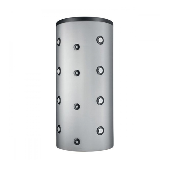
- Page 6 Budowa zbiornika buforowego SV (800, 1000l) [1] - króciec przyłączeniowy (6/4") [2] - króciec czujnika temperatury (1/2") [4] - króciec przyłącza odpowietrznika (6/4ʺ) [5] - stopki...
- Page 7 Budowa zbiornika buforowego SVW (800, 1000l) [1] - króciec przyłączeniowy (6/4") [2] - króciec czujnika temperatury (1/2") [4] - króciec przyłącza odpowietrznika (6/4ʺ) [5] - stopki [6] - króciec przyłącza wężownicy (6/4ʺ) PL;DE;FR;EN-061_f.1146...
- Page 8 Wymiary Model 1000 1000 1616 1596 1643 1761 1947 2132 1051 1120 1280 1303 1322 1338 1368 1446 1500 1774 1064 1120 1303 1239 1249 1278 1379 1500 1774 1021 1186 Instalacja • Zbiornik buforowy montuje się wyłącznie w pozycji pionowej. •...
-
Page 9: Dane Techniczne
Dane techniczne PL;DE;FR;EN-061_f.1146... - Page 10 Anwendungsbereich Die Pufferspeicher SV und SVW sind für das Aufbewahren von Warmwasser, in Zusammenarbeit mit Kesseln und Wärmepumpen, vorgesehen. Zusätzlich wirken sie als Verteiler (Kupplung), Hydraulikabscheider, Heizkreislauf aus dem Heizraum. Der Speicher SVW verfügt über ein Heizregister zum Anschluss einer Solaranlage.
- Page 11 Aufbau Aufbau des Pufferspeichers SV (200, 300, 400, 500l) [1] - Anschlussstutzen (6/4ʺ) [2] - Temperatursensorstutzen (1/2ʺ) [3] - Ablassstutzen (1/2ʺ), [4] - Entlüftungsanschlussstutzen (1/2ʺ) [5] - Stellfüsse PL;DE;FR;EN-061_f.1146...
- Page 12 Aufbau des Pufferspeichers mit Heizregister SVW (200, 300, 400, 500l) [1] - Anschlussstutzen (6/4ʺ) [2] - Temperatursensorstutzen (1/2ʺ) [3] - Ablassstutzen (3/4ʺ- 200, 300l), (1ʺ - 400l, 500l), [4] - Entlüftungsanschlussstutzen (1/2ʺ) [5] - Stellfüsse [6] - Anschlussstutzen des Heizregisters 1ʺ...
- Page 13 Aufbau des Pufferspeichers SV (800, 1000l) [1] - Anschlussstutzen (6/4ʺ) [2] - Temperatursensorstutzen (1/2ʺ) [4] - Entlüftungsanschlussstutzen (6/4ʺ) [5] - Stellfüsse PL;DE;FR;EN-061_f.1146...
- Page 14 Aufbau des Pufferspeichers mit Heizregister SVW (800, 1000l) [1] - Anschlussstutzen (6/4ʺ) [2] - Temperatursensorstutzen (1/2ʺ) [4] - Entlüftungsanschlussstutzen (6/4ʺ) [5] - Stellfüsse [6] - Anschlussstutzen des Heizregisters (6/4ʺ)
-
Page 15: Montage
Bemessung Modell 1000 1000 1616 1596 1643 1761 1947 2132 1051 1120 1280 1303 1322 1338 1368 1446 1500 1774 1064 1120 1303 1239 1249 1278 1379 1500 1774 1021 1186 Montage • Der Pufferspeicher darf ausschließlich in vertikaler Position montiert werden. •... -
Page 16: Technische Daten
Technische Daten... - Page 17 Destination Les ballons tampons SV et SVW sont destinés à stocker de l’eau chauffante en coopération avec des chaudières et des pompes de chaleur. En plus ils ont une fonction de séparateur hydraulique entre la chaudière et l’installation du chauffage central. Ballon tampon SVW est équipé...
- Page 18 Construction Construction du ballon tampon SV (200, 300, 400, 500l) [1] - orifice du raccordement (6/4ʺ) [2] - orifice pour doigt de gant (1/2ʺ) [3] - orifice de vidange (3/4ʺ- 200, 300l), (1ʺ - 400l, 500l), [4] - orifice pour purgeur (1/2ʺ)
- Page 19 Construction du ballon tampon avec le serpentin SVW (200, 300, 400, 500l) [1] - orifice du raccordement (6/4ʺ) [2] - orifice pour doigt de gant (1/2ʺ) [3] - orifice de vidange (3/4ʺ- 200, 300l), (1ʺ - 400l, 500l), [4] - orifice pour purgeur (1/2») [5] - pieds [6] - orifice du serpentin 1ʺ...
- Page 20 Construction du ballon tampon SV (800, 1000l) [1] - orifice du raccordement (6/4ʺ) [2] - orifice pour doigt de gant (1/2ʺ) [4] - orifice pour purgeur (6/4ʺ) [5] - pieds...
- Page 21 Construction du ballon tampon avec le serpentin SVW (800, 1000l) [1] - orifice du raccordement (6/4ʺ) [2] - orifice pour doigt de gant (1/2ʺ) [4] - orifice pour purgeur (6/4ʺ) [5] - pieds [6] - orifice du serpentin (6/4ʺ) PL;DE;FR;EN-061_f.1146...
-
Page 22: Installation
Dimensions Model 1000 1000 1616 1596 1643 1761 1947 2132 1051 1120 1280 1303 1322 1338 1368 1446 1500 1774 1064 1120 1303 1239 1249 1278 1379 1500 1774 1021 1186 Installation • Il faut poser le ballon tampon en position verticale. •... -
Page 23: Données Techniques
Données techniques PL;DE;FR;EN-061_f.1146... - Page 24 Application SV/SVW CH buffer tank is intended for storing the water. It’s suitable for co-operation with boilers and heat pumps. A buffer tank may also perform the following function: divider (hydraulic clutch), hydraulic separator, heating circuit from the boiler room.
- Page 25 Construction Buffer tank SV (200, 300, 400, 500l) [1] - connection stub (6/4ʺ) [2] - temperature sensor connector (1/2ʺ) [3] - drain connector (3/4ʺ- 200, 300l), (1ʺ - 400l, 500l) [4] - air vent connector (1/2ʺ) [5] - feet PL;DE;FR;EN-061_f.1146...
- Page 26 Buffer tank with heating coil SVW (200, 300, 400, 500l) [1] - connection stub (6/4") [2] - temperature sensor connector (1/2") [3] - drain connector (3/4"- 200, 300l), (1" - 400l, 500l) [4] - air vent connector (1/2") [5] - feet [6] - heating coil connector 1"...
- Page 27 Buffer tank SV (800, 1000l) [1] - connection stub (6/4") [2] - temperature sensor connector (1/2") [4] - air vent connector (6/4") [5] - feet PL;DE;FR;EN-061_f.1146...
- Page 28 Buffer tank with heating coil SVW (800, 1000l) [1] - connection stub (6/4") [2] - temperature sensor connector (1/2") [4] - air vent connector (6/4") [5] - feet [6] - heating coil connector (6/4")
- Page 29 Dimensions Model 1000 1000 1616 1596 1643 1761 1947 2132 1051 1120 1280 1303 1322 1338 1368 1446 1500 1774 1064 1120 1303 1239 1249 1278 1379 1500 1774 1021 1186 Installation • buffer tank is designed for vertical mounting only (screw feet), •...
-
Page 30: Technical Data
Technical data... - Page 32 KOSPEL Reparatur - Hotline 0241 910504 50 Technische Unterstützung (kostenlose) 0 800 18 62 155* *nur aus dem deutschen Festnetz erreichbar KOSPEL S.A. 75-136 Koszalin, ul. Olchowa 1 tel. +48 94 31 70 565 serwis@kospel.pl www.kospel.pl...
Need help?
Do you have a question about the SV and is the answer not in the manual?
Questions and answers