Advertisement
R
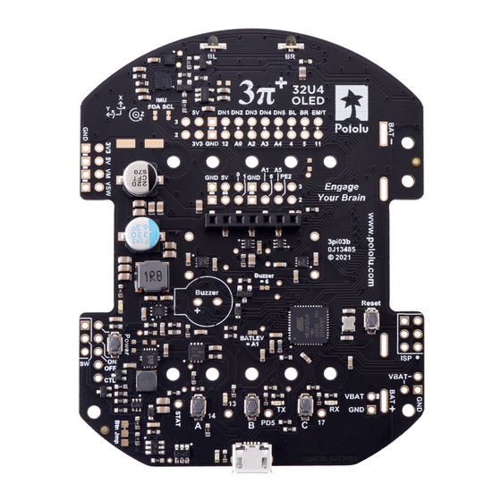
3pi+ 32U4 Control Board
© 2020 Pololu Corporation
®
www.pololu.com
SW1
USB Micro-B
VBUS
1
VBUS
2
D-
R3
3
D+
22
4
ID
5
GND
Y1 16 MHz
C4
10 pF
LCD
5V
1
Vss
2
VDD
R1
3
Vo
4
RS
D0
5
R/W
6
D1
E
7
DB0
8
DB1
9
DB2
10
DB3
11
D14
DB4
12
D17
DB5
13
D13
DB6
14
PD5
DB7
nRESET
ATmega32U4
13
RESET
7
R2
VBus
3
D-
4
22
D+
D17
(RXL/SS)
8
PB0 (SS/PCINT0)
D15
(SCK)
9
PB1 (PCINT1/SCK)
D16
(MOSI)
10
PB2 (PDI/MOSI/PCINT2)
D14
(MISO)
11
PB3 (PDO/MISO/PCINT3)
D8
28
PB4 (PCINT4/ADC11)
D9
29
PB5 (OC1A/OC4B/PCINT5/ADC12)
D10
30
PB6 (OC1B/OC4B/PCINT6/ADC13)
D11
12
PB7 (OC0A/OC1C/PCINT7/RTS)
PE2 (HWB)
D3
(SCL)
18
PD0 (INT0/SCL/OC0B)
PE6 (INT6/AIN0)
D2
(SDA)
19
PD1 (INT1/SDA)
D0
20
PD2 (INT2/RXD1)
D1
21
PD3 (INT3/TXD1)
PC6 (OC3A/OC4A)
D4
25
PD4 (ICP1/ADC8)
PC7 (ICP3/CLK0/OC4A)
PD5
(TXL)
22
PD5 (XCK1/CTS)
D12
26
PD6 (T1/OC4D/ADC9
D6
27
PD7 (T0/OC4D/ADC10)
PF7 (ADC7/TDI)
PF6 (ADC6/TDO)
PF5 (ADC5/TMS)
16
XTAL2
PF4 (ADC4/TCK)
PF1 (ADC1)
17
XTAL1
PF0 (ADC0)
C5
10 pF
5V
R6
1.5k
R8
D13
D14
R10
SW2
D2
2.21k
Button A
Green
PD5
R12
D4
R11
Yellow
1k
5V
L1
AVCC
10 uH
C1
0.1 uF
AVR3V3
6
UCap
C2
14
VCC
1 uF
34
5V
VCC
2
UVcc
AVCC
24
AVCC
44
AVCC
C3
42
AREF
AREF
0.1 uF
33
PE2
1
D7
31
D5
32
D13
36
A0
37
A1
38
A2
39
A3
40
A4
41
A5
5V
R7
2.21k
1k
R9
1.5k
D3
Red
D17
3k
R13
3k
SW3
SW4
Button B
Button C
Page 1 of 4
Front expansion header
Mid expansion header
EMIT
D11
BUMPR
D5
BUMPL
D4
DOWN5
A4
DOWN4
A3
DOWN3
A2
DOWN2
A0
DOWN1
D12
5V
3V3
1
1
2
2
D3
(SCL)
(SDA)
D2
3
3
5V
D1
Buzzer
D6
BZCTRL
Q1
R14
100k
Schematic diagram
Microcontroller and user interface
D3
(SCL)
(SDA)
D2
1
1
A5
PE2
2
2
A1
D6
3
3
5V
5V
4
4
D0
D1
5
5
6
6
7
7
5V
AVRISP
D14
1
2
MISO
VCC
D15
3
SCK
D16
4
MOSI
nRESET
5
6
RST
GND
VSW
R4
20k
A1
BATLEV
R5
10k
Advertisement
Table of Contents

Related Manuals for Pololu 3pi+ 32U4


Summary of Contents for Pololu 3pi+ 32U4
- Page 1 3pi+ 32U4 Control Board Schematic diagram © 2020 Pololu Corporation ® Microcontroller and user interface www.pololu.com AVCC 10 uH Front expansion header Mid expansion header 0.1 uF nRESET AVR3V3 (SCL) (SDA) ATmega32U4 USB Micro-B VBUS EMIT RESET UCap VBUS VBus...
- Page 2 3pi+ 32U4 Control Board Schematic diagram © 2020 Pololu Corporation ® Motors and encoders www.pololu.com DRV8838 DRV8838 0.1 uF 0.1 uF nSLEEP nSLEEP MLFRONT Left motor MRREAR Right motor GND (PPAD) OUT1 GND (PPAD) OUT1 MLREAR MRFRONT OUT2 OUT2 3.3 nF 0.1 uF...
- Page 3 3pi+ 32U4 Control Board Schematic diagram © 2020 Pololu Corporation ® Sensors www.pololu.com Bump sensors 10nF 10nF BUMPL BUMPR Inertial sensors EMIT 1 uF 0.1 uF 0.1 uF Line (reflectance) sensors EMIT EMIT 2.2nF DOWN5 LIS3MDL LSM6DS33 SCLLV SCL/SPC SCL/SPC...
- Page 4 3pi+ 32U4 Control Board Schematic diagram © 2020 Pololu Corporation ® Power www.pololu.com Simplified switch schematic VBAT VBAT 0.1 uF BAT1 (2x AAA) 100k 100k Btn Jmp 330 uF 10 uF 0.1 uF MODE VOUT 475k 0.1 uF 10 uF...
Need help?
Do you have a question about the 3pi+ 32U4 and is the answer not in the manual?
Questions and answers