
Subscribe to Our Youtube Channel
Related Manuals for OPTIMUM Maschinen OPTidrill B 34H


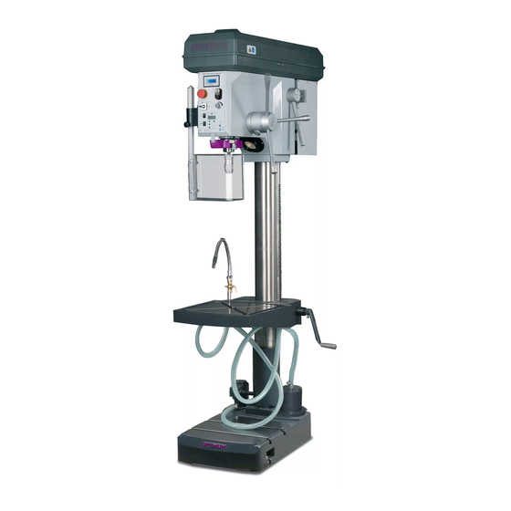
Summary of Contents for OPTIMUM Maschinen OPTidrill B 34H
- Page 1 Operating manual Version 1.1.3 Upright drilling machine Part no. 3020333 Part no. 3020335...
-
Page 2: Table Of Contents
Table of contents Safety Rating plates..............................6 Safety instructions (warning notes)........................ 7 1.2.1 Classification of hazards ........................7 1.2.2 Other pictograms..........................7 Intended use ..............................8 Reasonably foreseeable misuses........................9 1.4.1 Avoiding misuses ........................... 10 Possible dangers caused by the geared drill ....................10 Qualification of personnel .......................... - Page 3 4.5.1 Warming up the machine ........................32 4.5.2 Power supply ..........................32 Operation Control and indicating elements ........................33 Safety ................................34 5.2.1 Control panel B34H ........................34 5.2.2 Drill depth stop..........................35 5.2.3 Control panel B34 H Vario ......................35 Switching on the machine B34H ........................37 Switching on the machine B34HV ........................37 Switching off the machine B34HV ........................37 Digital drilling depth display ..........................37...
- Page 4 8.22 Schaltplan - Wiring diagram B34 H Vario 1- 2 ..................... 85 8.22.1 Schaltplan - Wiring diagram B34 H Varo 2-2 ................. 86 8.22.2 Ersatzteilliste elektrische Bauteile - Spare parts electrical components B34HV......87 Malfunctions Appendix 10.1 Copyright ..............................90 10.2 Terminology/Glossary..........................
- Page 5 If you have any further questions after reading these operating instructions and you are not able to solve your problem with a help of these operating instructions, please contact your specialised dealer or directly the company OPTIMUM. Optimum Maschinen Germany GmbH Dr. Robert-Pfleger-Str. 26 D-96103 Hallstadt...
-
Page 6: Safety
Always keep this documentation close to the geared drill. INFORMATION If you are unable to solve a problem using these operating instructions, please contact us for advice: Optimum Maschinen Germany GmbH Dr. Robert-Pfleger-Str. 26 D-96103 Hallstadt email: info@optimum-maschinen.de Rating plates... -
Page 7: Safety Instructions (Warning Notes)
Safety instructions (warning notes) 1.2.1 Classification of hazards We classify the safety warnings into various levels. The table below gives an overview of the classification of symbols (ideogram) and the warning signs for each specific danger and its (possible) consequences. Ideogram Warning alert Definition / consequence... -
Page 8: Intended Use
If the geared drill is used in any way other than described above, modified without authoriza- tion of Optimum Maschinen Germany GmbH, then the geared drill is being used improperly. We will not be held liable for any damages resulting from any operation which is not in accor- dance with the intended use. -
Page 9: Reasonably Foreseeable Misuses
Reasonably foreseeable misuses Any other use as the one determined under the "Intended use" or any use beyond the descri- bed use shall be deemed as not in conformity and is forbidden. Any other use has to be discussed with the manufacturer. It is only allowed to process metal, cold and non-inflammable materials with the geared drill. -
Page 10: Avoiding Misuses
1.4.1 Avoiding misuses Use of suitable cutting tools. Adapting the speed adjustment and feed to the material and workpiece. Clamp workpieces firmly and vibration-free. ATTENTION! The workpiece is always to be fixed by a machine vice, jaw chuck or by another appropriate clamping tool such as for the clamping claws. -
Page 11: Qualification Of Personnel
the correct function of the geared drill may be affected. Always disconnect the geared drill if cleaning or maintenance work is being carried out, or is no longer in use. WARNING! The geared drill may only be used with the safety devices activated. Disconnect the geared drill immediately whenever you detect a failure in the safety devices or when they are not mounted! All additional devices installed by the operator have to be equipped with the prescribed... -
Page 12: Authorized Persons
1.6.2 Authorized persons WARNING! Inappropriate operation and maintenance of the geared drill constitutes a danger for the staff, objects and the environment. Only authorized staff may operate the geared drill! Persons authorized to operate and maintain should be trained technical staff and instructed by the ones who are working for the operating company and for the manufacturer. -
Page 13: Safety Measures During Operation
Abb.1-1: Operator positions Safety measures during operation CAUTION! Risk due to inhaling of health hazardous dusts and mist. Dependent on the material which need to be processed and the used auxiliaries dusts and mist may be caused which might impair you health. Make sure that the generated health hazardous dusts and mist are safely sucked off at the point of origin and is dissipated or filtered from the working area. -
Page 14: Emergency-Stop Push Button
once a week (with the machine in operation), after every maintenance and repair work. Check that prohibition, warning and information signs and the labels on the geared drill are legible (clean them, if necessary), are complete (replace if necessary). INFORMATION Use the following table in order to organize the checks. -
Page 15: Drilling Table
1.12 Drilling table Seats for T-slots are atta- ched to the drilling table. WARNING! Risk injury workpieces flying off at high speed. Securely fix the workpiece on the drilling table. Holding fixture for inserted tongues Abb.1-3: Drilling table 1.13 Separating protective devices 1.13.1 Protective cover of the V-belts A protective cover for the belt pul- leys is mounted on the drilling... -
Page 16: Personnel Protective Equipment
INFORMATION You cannot start the machine if the drill chuck protection is not closed. Abb.1-5: Drill chuck protection 1.14 Personnel protective equipment For certain work individual protection gear as protective equipment. This includes: Safety helmet, Protective goggles or face guard, ... -
Page 17: Safety During Operation
1.15 Safety during operation We specially point out the specific dangers when working with and on the geared drill. WARNING! Before switching on the geared drill make sure that there are no no dangers generated for persons, not cause damage to equipment. Avoid any risky working practices: ... -
Page 18: Mechanical Maintenance Work
Check if they are working properly! 1.18 Accident report Inform your superiors and Optimum Maschinen Germany GmbH immediately in the event of accidents, possible sources of danger and any actions which almost led to an accident (near misses). There are many possible causes for "near misses". -
Page 19: Technical Data
Technical data The following information are the dimensions and indications of weight and the manufacturer‘s approved machine data. Electrical connection B34H B34HV 400V ~50 Hz 230V ~50 Hz Connection 1.5 kW / 2.2 kW 2.2 kW Coolant pump B34H B34HV 230V ~50 Hz Motor power 40 W... -
Page 20: Emissions
Required space B34H B34HV Height [mm] 2500 Depth [mm] 1700 Width [mm] 1500 Weight [kg] Speeds B34H B34HV Spindle speeds [ min 145 - 4800 40 - 5000 Number of stages 2 x 9 Environmental conditions B34H B34HV Temperature 5 - 35 °C Relative humidity 25 - 80 % Operating material... - Page 21 This information about the noise emission shall allow the operator of the machine to more easily evaluate the endangering and risks. CAUTION! Depending on the overall noise exposure and the basic limit values the machine operators must wear an appropriate hearing protection. We generally recommend to use a noise protection and a hearing protection.
-
Page 22: Dimensions B34H
2.11 Dimensions B34H 495,5 Schwerpunkt/ Centre of gravity Abb.2-1: Dimensions B34H B34H | B34HV Technical data Translation of the original instructions Version 1.1.3 - 2020-07-21... -
Page 23: Dimensions B34Hv
2.12 Dimensions B34HV 495,5 Schwerpunkt/ Centre of gravity Abb.2-2: Dimensions B34HV Technical data B34H | B34HV Version 1.1.3 - 2020-07-21 Translation of the original instructions... -
Page 24: Delivery, Interdepartmental Transport And Unpacking
Delivery, interdepartmental transport and unpacking CAUTION! Injuries caused by parts falling over or off a forklift, pallet truck or transport vehicle. Only use means of transport that can carry the total weight and are suitable for it. Notes on transport, installation and unpacking Improper transport of individual devices and minor machines, unsecured devices and minor machines stacked on top of each other or next to each other in packed or already unpacked condition is accident-prone and can cause damage or malfunctions for which we do not grant... -
Page 25: Assembly 4.1 Scope Of Delivery
Assembly Scope of delivery When the machine is delivered, check immediately that the machine has not been damaged during transport and that all components are included. Compare the parts supplied the informa- tion on the packaging list. 4.1.1 Available optional machine accessories Designation Item number Machine vice MSO 100... - Page 26 Hexagon socket screws are provided to fix the drilling column with the base. Drill column Hexagon socket screws Base Abb.4-1: Assembling drill column B34H Vario Drill column Hexagon socket screws Base Abb.4-2: Assembling drill column B34H B34H | B34HV Assembly Translation of the original instructions Version 1.1.3 - 2020-07-21...
-
Page 27: Mounting The Drilling Table
4.2.3 Mounting the drilling table Push the toothed rod into the drilling table Adjust the toothed rod within the drilling table in a way that Drilling table the teeth of the toothed rod came in with the worm gear of the drilling table. - Page 28 Mount axial bearing, bushing and clamping lever. Drilling table Bushing Axial bearing Clamping lever Abb.4-5: Assembling drilling table Mount cooling equipment. Mount all cooling agent hoses and fasten you these with the hose clamps. Drilling table Coolant equipment Drill column Cooling agent hoses Abb.4-6:...
-
Page 29: Fitting The Drill Head
4.2.4 Fitting the drill head Put the intermediate plate on the drilling column. Fix the intermediate plate with Cap screws the cap screws on the drilling column. Put the drilling head on the intermediate plate and turn it Intermediate plate as much until is aligned with the stand. -
Page 30: Fixing
Fixing In order to provide for the necessary stability of the geared drill, it is necessary to firmly bolt the base of the machine to the subsurface. We recommend you to use shear connector cartridges resp. heavy-duty anchors. Fix the foot of the geared drill to the substructure with the provided through-holes. -
Page 31: Installation Drawings
4.4.1 Installation drawings B34H Fixing 2x Abb.4-11: B34H B34HV Fixing 3x Abb.4-12: B34HV First commissioning ATTENTION! Before commissioning the machine check all screws, fixtures resp. safety devices and tighten up the screws if necessary! WARNING! Risk by using improper tool holders or operating them at inadmissible speeds. Only use the tool holders (e.g. -
Page 32: Warming Up The Machine
It is only allowed to modify tool holding fixtures in compliance with the recommendati- ons of OPTIMUM or the manufacturer of the clamping device. WARNING! When first commissioning the geared drill by inexperienced staff you endanger people and the machine. We do not take any liability for damages caused by incorrectly performed commissioning. -
Page 33: Operation
Operation Control and indicating elements B34H B34HV Pos. Designation Pos. Designation Belt drive with housing Lever for spindle sleeve feed EMERGENCY-STOP button Push button ON / OFF Drill chuck protection Drilling table Table height adjustment Switch Coolant equipment Chip filter Coolant pump Operation B34H | B34HV... -
Page 34: Safety
Safety Use the machine only under the following conditions: The machine is in proper working order. The machine is used as prescribed. The operating manual is followed. All safety devices are installed and activated. All failures should be eliminated immediately. Stop the machine immediately in the event of any anomaly in operation and make sure it cannot be started up accidentally or without authoriza- tion Notify the person responsible immediately of any modification. -
Page 35: Drill Depth Stop
Operating control lamp The operating control lamp on the operating panel has to flash. Machine illumination ON/OFF Switches the illumination on or off. Main switch Main switch Machine illumination Interrupts or connects the power sup- ply. Abb.5-2: Machine illumination B34H 5.2.2 Drill depth stop When... - Page 36 Selection switch for operating mode With the selector switch the operating mode „Auto, threading or right-hand respectively left- hand run“ is being selected. Operating mode „Auto“ In the automatic mode the engine starts up according to a predefined path over the dril- Digital display ling depth limit of the spindle sleeve and stop Drilling depth...
-
Page 37: Switching On The Machine B34H
Main switch Interrupts or connects the power supply. Switching on the machine B34H Switch on the main switch. Select the direction of rotation. Actuate the push button „ON“. Switching on the machine B34HV Switch on the main switch. ... -
Page 38: Design
5.6.1 Design Off - switch LCD display Conversion mm/inch On - switch On switch Zeroing Battery bay Value increase Value decrease Abb.5-7: Digital display ON / O, switches the display on and resets the reading of the display to "0". ... -
Page 39: Speed Change
Speed change WARNING! Danger due to drill chuck or tools flying off at high speed. Make sure not to exceed the maximum speed of the drill chuck when setting the spindle speed. Switch off the machine by pressing the main switch. ... -
Page 40: Speed Table B34 H
5.7.1 Speed table B34 H Abb.5-10: Speed table B34H 5.7.2 Speed table B34HV Abb.5-11: Speed table B34HV B34H | B34HV Operation Translation of the original instructions Version 1.1.3 - 2020-07-21... -
Page 41: Disassembly, Assembly Of Drill Chucks And Drill Bits
Disassembly, assembly of drill chucks and drill bits 5.8.1 Mounting drill chuck B34H / B34HV The quick-action drill chuck is secured through a form- fit union (driver) against twisting drilling Drill sleeve spindle. friction-locking union holds centers quick-action drill chuck Driver with the taper mandrel in the drilling spindle. -
Page 42: Disassembly With The Integrated Drill Drift B34H / B34Hv
5.8.3 Disassembly with the integrated drill drift B34H / B34HV ATTENTION! The tool and/or the drill chuck will fall down. Hold the tool or the drill chuck while drifting it out. ATTENTION! Do not try to expel the tool when it is in the intermediate position. -
Page 43: Cooling
Cooling WARNING! Ejection and overflowing of coolants and lubricants. Make sure you do not get the cooling lubricants on the floor. Spilled on the floor cooling agents must be removed immediately. The friction generated during rotation can cause the edge of the tool to become very hot. The tool should be cooled during the drilling process. -
Page 44: Before Starting Work
5.10 Before starting work Before starting work, select the desired speed. It is depending on the used drilling diameter and on the material. Determining the cutting speed and the speed on page 46 Speed table B34 H on page 40, Speed table B34HV on page 40 INFORMATION The data of the speed tables are guide values. -
Page 45: During Work
5.11 During work The spindle sleeve is advanced by means of the star wheel. Make sure that the feed is constant and not too fast. The spindle sleeve is returned to its initial position by the return spring. WARNING! Seizing of clothes and / or hair. ... -
Page 46: Determining The Cutting Speed And The Speed
Determining the cutting speed and the speed Table cutting speeds / infeed Material table Recommended infeed f in mm/revolution Recommended Material to be processed cutting speed Drill bit diameter d in mm Vc in m/min 2...3 >3...6 >6...12 >12...25 >25...50 Unalloyed construction steels 30 - 35 0.05... - Page 47 Drill bit Ø Speed n in rpm in mm 1062 1274 1415 1769 2123 2477 2831 3539 4246 5662 7077 1146 1274 1592 1911 2229 2548 3185 3822 5096 6369 1042 1158 1448 1737 2027 2316 2895 3474 4632 5790 1062 1327 1592...
-
Page 48: Examples To Calculatory Determine The Required Speed For Your Drilling Machine
Drill bit Ø Speed n in rpm in mm 39,0 40,0 41,0 42,0 43,0 44,0 45,0 46,0 47,0 48,0 49,0 50,0 Examples to calculatory determine the required speed for your drilling machine The necessary speed is depending on the diameter of the drill bit, on the material which is being machined as well as on the cutting material of the drill bit. -
Page 49: Maintenance
Maintenance In this chapter you will find important information about Inspection Maintenance Repairs ATTENTION! Properly performed regular maintenance is an essential prerequisite for operational safety, failure-free operation, long service life of the machine and ... -
Page 50: Restarting
7.1.2 Restarting Before restarting run a safety check. Safety check on page 13 WARNING! Before starting the machine you must be sure that no dangers generated for persons, the machine is not damaged. Inspection and maintenance The type and level of wear depends to a large extent on the individual usage and operating conditions. - Page 51 Interval Where? What? How? Any unusual rattling noises can be eliminated by regreasing. The sleeve (1) moves downwards or upwards with the toothed spindle (2) in the fixed driven sleeve (3) during drill feed. The noises are caused by the necessary clearance between the two toothings of the sleeve and spindle.
- Page 52 Interval Where? What? How? Check whether the V-belts have become porous and worn. every six mon- V-belt Img.7-3: V-belt housing B34 H/ B34 H Vario Lubricate all oilers with machine oil, do not use grease guns or the like. ...
- Page 53 Interval Where? What? How? If the light bulb is defective: Disconnect the machine from the mains. Unscrew the glass cover of the machine illumination. Unscrew the light bulb by turning it to the left and by slightly pressing the bulb into the socket (bayonet).
-
Page 54: Repair
If the repairs are carried out by qualified technical personnel, they must follow the indications given in these operating instructions. Optimum Maschinen Germany GmbH accepts no liability nor does it guarantee against damage and operating malfunctions resulting from failure to observe these operating instructions. -
Page 55: Ersatzteile - Spare Parts
Ersatzteile - Spare parts Ersatzteilbestellung - Ordering spare parts Bitte geben Sie folgendes an - Please indicate the following : Seriennummer - Serial No. Maschinenbezeichnung - Machines name Herstellungsdatum - Date of manufacture Artikelnummer - Article no. Die Artikelnummer befindet sich in der Ersatzteilliste. -
Page 56: Bohrkopf B34H - Drilling Head B34H
Bohrkopf B34H - Drilling head B34H Abb.8-1: Bohrkopf B34H - Drilling head B34H DE | GB B34H | B34HV Originalbetriebsanleitung Version 1.1.3 - 2020-07-21... -
Page 57: Bohrkopf 1 Von 5 - Drilling Head 1 Of 5
Bohrkopf 1 von 5 - Drilling head 1 of 5 Abb.8-2: Bohrkopf 1 von 5 - Drilling head 1 of 5 B34H | B34HV DE | GB Version 1.1.3 - 2020-07-21 Originalbetriebsanleitung... - Page 58 Bohrkopf 2 von 5 - Drilling head 2 of 5 Abb.8-3: Bohrkopf 2 von 5 - Drilling head 2 of 5 DE | GB B34H | B34HV Originalbetriebsanleitung Version 1.1.3 - 2020-07-21...
-
Page 59: Ersatzteilzeichnung Bohrkopf 3 Von 5 - Parts Drawing Drilling Head 3 Of 5
Ersatzteilzeichnung Bohrkopf 3 von 5 - Parts drawing drilling head 3 of 5 Abb.8-4: Bohrkopf 3 von 5 - Drilling head 3 of 5 B34H | B34HV DE | GB Version 1.1.3 - 2020-07-21 Originalbetriebsanleitung... -
Page 60: Bohrkopf 4 Von 5 - Drilling Head 4 Of 5
Bohrkopf 4 von 5 - Drilling head 4 of 5 Abb.8-5: Bohrkopf 4 von 5 - Drilling head 4 of 5 DE | GB B34H | B34HV Originalbetriebsanleitung Version 1.1.3 - 2020-07-21... - Page 61 Bohrkopf 5 von 5 - Drilling head 5 of 5 Abb.8-6: Bohrkopf 5 von 5 - Drilling head 5 of 5 B34H | B34HV DE | GB Version 1.1.3 - 2020-07-21 Originalbetriebsanleitung...
-
Page 62: Bohrfutterschutz - Drilling Chuck Protection
8.9.1 Bohrfutterschutz - Drilling chuck protection Abb.8-7: Bohrfutterschutz - Drilling chuck protection DE | GB B34H | B34HV Originalbetriebsanleitung Version 1.1.3 - 2020-07-21... -
Page 63: Säule Und Bohrtisch - Column And Drilling Table
8.9.2 Säule und Bohrtisch - Column and drilling table 134 135 169-ab/from 2019 Abb.8-8: Säule und Bohrtisch - Column and drilling table B34H | B34HV DE | GB Version 1.1.3 - 2020-07-21 Originalbetriebsanleitung... -
Page 64: Maschinenschilder - Machine Labels B34H
8.10 Maschinenschilder - Machine labels B34H Abb.8-9: Maschinenschilder - Machine labels B34H B34H Menge Grösse Artikelnummer Bezeichnung Designation Qty. Size Item no. Gehäuse Casing Sicherungsring Retaining ring DIN 472 - 68x2,5 042SR68I Kugellager Ball bearing 6008-2RZ 0406008R Spindel Spindle 0302033304 Sicherungsring Retaining ring DIN 471 - 40 x 1,75... - Page 65 Spiralfeder Spiral spring 0302130333 Federsitz Spring seat 0302033324 Zylinderstift Straight pin GB 119-86 - B 6 x 32 0302033325 Abdeckung Cover 0302033326 Flansch Flange 0302033327 Innensechskantschraube Socket head screw GB 70-85 - M8 x 30 Gewindestift Grub screw ISO 4028 - M8 x 30 0302033329 Skalenring Graduated collar...
- Page 66 Anzeige Advert 0302033367 Bolzen Bolt 0302033368 Hebel Lever 0302033369 Sechskantmutter Hexagon nut GB 6170-86 - M12 Feder Spring 0302033371 Arbeitsleuchte Lamp 03334400EL1 Hauptschalter Main switch 0302024187 Scheibe Washer DIN 125 - A 5,3 Welle Shaft 0302033375 Verstellschraube Adjusting screw 0302033376 Buchse Bushing 0302130388...
- Page 67 Innensechskantschraube Socket head screw GB 70-85 - M10 x 35 Passfeder Fitting key DIN 6885 - A 8 x 7 x 45 042P8745 Keilriemenscheibe V- belt pulley 03020333114 CPL Keilriemenscheibe komplett V-belt pulley complete 03020333114CPL Keilriemenscheibe V- belt pulley 03020333115 Keilriemen V- Belt 11M975...
- Page 68 Standfuss Base 03020333158 Klemmleiste Terminal block 03021303201CB Deckel Cover Schaltkasten Switch box Kabelentlastung Cable discharge Power pack rotation speed Netzteil Drehzahlanzeige 03020333164 indicator Lüfterrad Fan wheel Motordeckel Motor cover Gleitlager Plain bearing 40x44x13 03020333167 Gleitlager Plain bearing 40x44x30 03020333168 Bohrtisch Drilling table ab/from 2019 03020333169...
-
Page 69: Schaltplan - Wiring Diagram B34 H
8.11 Schaltplan - Wiring diagram B34 H Abb.8-10: Schaltplan - Wiring diagram B34H B34H | B34HV DE | GB Version 1.1.3 - 2020-07-21 Originalbetriebsanleitung... -
Page 70: Ersatzteilliste Elektrische Bauteile - Spare Parts Electrical Components - B34H
8.11.1 Ersatzteilliste elektrische Bauteile - Spare parts electrical components - B34H Ersatzteilliste elektrische Bauteile - Spare parts electrical components B34H Menge Grösse Artikelnummer Bezeichnung Designation Qty. Size Item no. Hauptschalter Main switch Spindelmotor Spindle motor Drehrichtung/Geschwindigkeitsschalter Change-over switch siehe Zeichnung / see drawing Drehzahlsensor Rotation speed sensor... -
Page 71: Ersatzteilzeichnung B34Hv - Explosion Drawing B34Hv
8.12 Ersatzteilzeichnung B34HV - Explosion drawing B34HV 8.13 Bohrkopf B34HV - Drilling head B34HV Abb.8-11: Bohrkopf - Drilling head B34H | B34HV DE | GB Version 1.1.3 - 2020-07-21 Originalbetriebsanleitung... -
Page 72: Bohrkopf 1 Von 5 - Drilling Head 1 Of 5
8.14 Bohrkopf 1 von 5 - Drilling head 1 of 5 Abb.8-12: Bohrkopf 1 von 5 - Drilling head 1 of 5 DE | GB B34H | B34HV Originalbetriebsanleitung Version 1.1.3 - 2020-07-21... - Page 73 8.15 Bohrkopf 2 von 5 - Drilling head 2 of 5 Abb.8-13: Bohrkopf 2 von 5 - Drilling head 2 of 5 B34H | B34HV DE | GB Version 1.1.3 - 2020-07-21 Originalbetriebsanleitung...
-
Page 74: Bohrkopf 3 Von 5 - Drilling Head 3 Of 5
8.16 Bohrkopf 3 von 5 - Drilling head 3 of 5 Abb.8-14: Bohrkopf 3 von 5 - Drilling head 3 of 5 DE | GB B34H | B34HV Originalbetriebsanleitung Version 1.1.3 - 2020-07-21... -
Page 75: Bohrkopf 5 Von 5 - Drilling Head 5 Of 5
8.17 Bohrkopf 4 von 5 - Drilling head 4 of 5 Abb.8-15: Bohrkopf 4 von 5 - Drilling head 4 of 5 B34H | B34HV DE | GB Version 1.1.3 - 2020-07-21 Originalbetriebsanleitung... - Page 76 8.18 Bohrkopf 5 von 5 - Drilling head 5 of 5 Abb.8-16: Bohrkopf 5 von 5 - Drilling head 5 of 5 DE | GB B34H | B34HV Originalbetriebsanleitung Version 1.1.3 - 2020-07-21...
-
Page 77: Bohrfutterschutz - Drilling Chuck Protection
8.19 Bohrfutterschutz - Drilling chuck protection Abb.8-17: Bohrfutterschutz - Drilling chuck protection B34H | B34HV DE | GB Version 1.1.3 - 2020-07-21 Originalbetriebsanleitung... -
Page 78: Säule Und Bohrtisch - Column And Drilling Table
8.20 Säule und Bohrtisch - Column and drilling table 159 160 195-ab/from 2019 Abb.8-18: Säule und Bohrtisch - Column and drilling table DE | GB B34H | B34HV Originalbetriebsanleitung Version 1.1.3 - 2020-07-21... -
Page 79: Maschinenschilder - Machine Labels B34Hv
8.21 Maschinenschilder - Machine labels B34HV Abb.8-19: Maschinenschilder - Machine labels B34HV 8.21.1 Ersatzteilliste - Spare part list - B34HV B34HV Menge Grösse Artikelnummer Bezeichnung Designation Qty. Size Item no. Gehäuse Casing Sicherungsring Retaining ring DIN 472 - 68x2,5 042SR68I Kugellager Ball bearing 6008-2RZ... - Page 80 Hülse Bushing 0302033314 Zylinderstift Straight pin GB 119-86 - B 10 x 50 Ring Ring 0302033316 Feder Spring 0302033317 Kegelrollenlager Taper roller bearing 30208 J2_Q 04030208 Scheibe Washer 0302033319 Halter Bracket 0302033320 Digitalanzeige/ Messleiste Digital display 0302033321 Zahnrad Gear 0302033322 Spiralfeder Spiral spring 0302130333...
- Page 81 Platte Plate 0302033561 Innensechskantschraube Socket head screw GB 70-85 - M6 x 20 Brushlesscontroller Brushlesscontroller 0302BCV323 63-1 Klemmleiste Terminal block Innensechskantschraube Socket head screw GB 70-85 - M6 x 10 Innensechskantschraube Socket head screw GB 70-85 - M3 x 6 Scheibe Washer DIN 125 - A 3,2...
- Page 82 Bolzen Bolt Feder Spring Stahlkugel Steel ball 6,3mm 042KU63 Schild Label Potentiometer Potentiometer 03338120R1.5 Schalter Arbeitsleuchte Switch light 0460005 111-1 Schalter Kühlmittelpumpe Switch coolant pump 0460005 Schalter Switch 0460008 Not-Halt Schalter Emergency stop button 0460058 Ein- Aus Schalter Switch on/off 03338120S1.3 Platte Plate...
- Page 83 Kühlmittelschlauch Coolant hose 0333440025 Schlauchtülle Hose clip 03020335153 Kühlmittelpumpe Coolant pump 0302130349 Platte Pumpe Plate pump 03020335155 Standfuss Base 03020335156 Innensechskantschraube Socket head screw GB 70-85 - M14x50 Zwischenplatte Distance plate Buchse Protection bush Axiallager Axial bearing 51103/17x30x9 04051103 Stiftschraube Locking screw Klemmhebel Clamping lever...
- Page 84 Sicherheitsschild Safety label Frontschild Front label Sicherheitsschild Safety label Hinweisschild Instruction label Hinweisschild Instruction label DE | GB B34H | B34HV Originalbetriebsanleitung Version 1.1.3 - 2020-07-21...
-
Page 85: Schaltplan - Wiring Diagram B34 H Vario 1- 2
8.22 Schaltplan - Wiring diagram B34 H Vario 1- 2 Abb.8-20: Schaltplan - Wiring diagram B34HV 1-2 B34H | B34HV DE | GB Version 1.1.3 - 2020-07-21 Originalbetriebsanleitung... -
Page 86: Schaltplan - Wiring Diagram B34 H Varo 2-2
8.22.1 Schaltplan - Wiring diagram B34 H Varo 2-2 Abb.8-21: Schaltplan - Wiring diagram B34HV 2-2 DE | GB B34H | B34HV Originalbetriebsanleitung Version 1.1.3 - 2020-07-21... -
Page 87: Ersatzteilliste Elektrische Bauteile - Spare Parts Electrical Components B34Hv
8.22.2 Ersatzteilliste elektrische Bauteile - Spare parts electrical components B34HV B34HV - Ersatzteilliste elektrische Bauteile - Spare parts electrical components Menge Grösse Artikelnummer Bezeichnung Designation Qty. Size Item no. Hauptschalter Main switch Brushlesscontroller Brushlesscontroller Type V3.23 Sicherung Fuse Netzfilter Line filter 1B1.2 Sicherheitsschalter Bohrfutterschutz Drilling chuck safety switch Not-Halt Schalter... -
Page 88: Malfunctions
Malfunctions Cause/ Malfunction Solution possible effects FI protective • an unusual • Power supply on page 32 switch on machines with FI protective switch is being used frequency converter triggers. Motor is getting hot • Wrong electrical connection of 400 V machines Noise during work. - Page 89 Cause/ Malfunction Solution possible effects Spindle bearing overheating • Bearing worn down • Replace • Bearing pretension is too high • Increase bearing clearance for fixed bearing (taper roller bearing) • Working at high drilling speed over • Reduce drill speed and feed rate a longer period of time.
-
Page 90: Appendix 10.1 Copyright
Appendix 10.1 Copyright This document is copyright. All derived rights are also reserved, especially those of translation, re-printing, use of figures, broadcast, reproduction by photo-mechanical or similar means and recording in data processing systems, neither partial nor total. Subject to technical changes without notice. 10.2 Terminology/Glossary Term... -
Page 91: Liability Claims For Defects / Warranty
Any defective products or components of such products will either be repaired or replaced by components which are free from defects. The property of replaced pro- ducts or components passes on to OPTIMUM Maschinen Germany GmbH. The automatically generated original proof of purchase which shows the date of purchase, the type of machine and the serial number, if applicable, is the precondition in order to assert liability or warranty claims. -
Page 92: Decommissioning
10.5.1 Decommissioning CAUTION! Used devices need to be decommissioned in a professional way in order to avoid later misuses and endangerment of the environment or persons. Disconnect the plug from the power supply. Cut the connection cable. Remove all environmentally hazardous operating fluids from the used device. -
Page 93: Disposal Of Lubricants And Coolants
10.5.5 Disposal of lubricants and coolants ATTENTION! Please imperatively make sure to dispose of the used coolant and lubricants in an environmentally compatible way. Observe the disposal notes of your municipal waste management companies. INFORMATION Used coolant emulsions and oils should not be mixed up since it is only possible to reuse used oils which had not been mixed up without pre-treatment. -
Page 94: Product Follow-Up
Consult Optimum Maschinen Germany GmbH if the machine and accessories are stored for more than three months or are stored under different environmental conditions than those given here Information on page 6. 10.8 Product follow-up We are required to perform a follow-up service for our products which extends beyond ship- ment. - Page 95 EC - Declaration of Conformity - B34H according to Machinery directive 2006/42/EC, Annex II 1.A The manufacturer / distributor Optimum Maschinen Germany GmbH Dr.-Robert-Pfleger-Str. 26 D - 96103 Hallstadt, Germany hereby declares that the following product Product designation: Drilling machine...
- Page 96 EC - Declaration of Conformity - B34HV according to Machinery directive 2006/42/EC, Annex II 1.A The manufacturer / distributor Optimum Maschinen Germany GmbH Dr.-Robert-Pfleger-Str. 26 D - 96103 Hallstadt, Germany hereby declares that the following product Product designation: Drilling machine...
- Page 97 Index Accident report ............18 Safety Assembling during maintenance ......... 17 drill head ............29 during operation ..........17 drilling table ............27 Safety devices ............13 Assembly ..............25 Safety instructions ..........7 Scope of delivery ..........25 Selection switch Classification of hazards .........7 for operating mode ..........
- Page 98 Quellenverzeichnis von Ihrem Fachhändler Metallbau Mehner Optimum Bohrmaschinen: OPTIdrill B 34 H • ◦ OPTIdrill B 34 H Ersatzteile ◦ OPTIdrill B 34 H Zubehör OPTIdrill B 34 HV • ◦ OPTIdrill B 34 HV Ersatzteile ◦ OPTIdrill B 34 HV Zubehör OPTIdrill Zubehör •...
Need help?
Do you have a question about the OPTidrill B 34H and is the answer not in the manual?
Questions and answers