Table of Contents
Advertisement
Quick Links
Freescale Semiconductor, Inc.
User's Guide
Freescale Freedom Development
Board FRDM-CR20A User's Guide
1
About this guide
This User's Guide describes the Freescale FRDM-CR20A
development board. The FRDM-CR20A is a 2.4 GHz
Industrial, Scientific, and Medical (ISM) intended for the
IEEE® 802.15.4 Standard, including Thread and
IPv6/6loWPAN protocols. The FRDM-CR20A contains the
MCR20A transceiver that is typically combined with a
software stack and a Freescale Kinetis MCU to implement
an IEEE 802.15.4 Standard platform solutions.
1.1
Audience
This manual is intended for system designers.
2
Safety information
2.1
FCC guidelines
This equipment is for use by developers for evaluation
purposes only and must not be incorporated into any other
device or system. This device may not be sold to the general
public. Integrators will be responsible for reevaluating the
end product (including the transmitter) and obtaining a
separate FCC authorization.
© 2015 Freescale Semiconductor, Inc. All rights reserved.
Arrow.com.
Downloaded from
Document Number: FRDMCR20AUG
Contents
1. About this guide . . . . . . . . . . . . . . . . . . . . . . . . . . . . . 1
1.1. Audience . . . . . . . . . . . . . . . . . . . . . . . . . . . . . . . . . . . 1
2. Safety information . . . . . . . . . . . . . . . . . . . . . . . . . . . 1
2.1. FCC guidelines . . . . . . . . . . . . . . . . . . . . . . . . . . . . . . 1
2.2. Regulatory approval for Canada (IC RSS 210) . . . . . 2
2.3. Electrostatic discharge considerations . . . . . . . . . . . . 3
2.4. Disposal instructions . . . . . . . . . . . . . . . . . . . . . . . . . 3
3.1. Introduction . . . . . . . . . . . . . . . . . . . . . . . . . . . . . . . . 3
3.2. Board features . . . . . . . . . . . . . . . . . . . . . . . . . . . . . . . 4
3.3. Software and driver considerations . . . . . . . . . . . . . . 5
4. FRDM-CR20A development board . . . . . . . . . . . . . . 5
4.1. FRDM-CR20A board overview . . . . . . . . . . . . . . . . . 5
4.2. Functional description . . . . . . . . . . . . . . . . . . . . . . . . 9
4.3. Schematic, board layout, and bill of material . . . . . . 15
5. PCB manufacturing specifications . . . . . . . . . . . . . . 20
5.1. Single PCB construction . . . . . . . . . . . . . . . . . . . . . 21
5.2. Panelization . . . . . . . . . . . . . . . . . . . . . . . . . . . . . . . 22
5.3. Materials . . . . . . . . . . . . . . . . . . . . . . . . . . . . . . . . . . 22
5.4. Solder mask . . . . . . . . . . . . . . . . . . . . . . . . . . . . . . . 22
5.5. Silk screen . . . . . . . . . . . . . . . . . . . . . . . . . . . . . . . . 22
5.6. Electrical PCB testing . . . . . . . . . . . . . . . . . . . . . . . 23
5.7. Packaging . . . . . . . . . . . . . . . . . . . . . . . . . . . . . . . . . 23
5.8. Hole specification/tool table . . . . . . . . . . . . . . . . . . . 23
5.9. File description . . . . . . . . . . . . . . . . . . . . . . . . . . . . . 23
6. Revision history . . . . . . . . . . . . . . . . . . . . . . . . . . . . 23
Rev. 0, 04/2015
Advertisement
Table of Contents

Subscribe to Our Youtube Channel
Related Manuals for NXP Semiconductors Freescale FRDM-CR20A


Summary of Contents for NXP Semiconductors Freescale FRDM-CR20A
-
Page 1: Table Of Contents
1.1. Audience ........1 This User’s Guide describes the Freescale FRDM-CR20A 2. -
Page 2: Regulatory Approval For Canada (Ic Rss 210)
Safety information FCC approval of this device only covers the original configuration of this device as supplied. Any modifications to this product, including changes shown in this manual, may violate the rules of the Federal Communications Commission and Industry Canada and make operation of the product unlawful. 2.1.1 Labeling FCC labels are physically located on the back of the board. -
Page 3: Electrostatic Discharge Considerations
MCR20A transceiver overview and description 2.2.1 26 PART 5 – Appendix Le présent appareil est conforme aux CNR d'Industrie Canada applicables aux appareils radio exempts de licence. L'exploitation est autorisée aux deux conditions suivantes: 1. l'appareil ne doit pas produire de brouillage, et 2. -
Page 4: Board Features
MCR20A transceiver overview and description The FRDM-CR20A development board consists of one board that contains the MCR20A device with a 32 MHz reference oscillator crystal, RF circuitry including an antenna, and supporting circuitry to be mounted into the popular Freescale Freedom development board form factor. The board is not a standalone product;... -
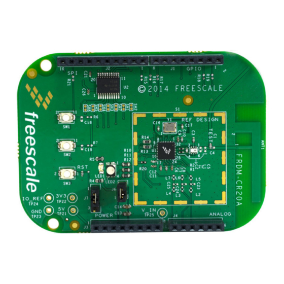
Page 5: Software And Driver Considerations
• Provides access to the MCR20AVHM set of GPIOs Figure 2 shows the main board features and Input/Output headers for the Freescale FRDM-CR20A board. Figure 2. FRDM-CR20A callouts and I/O headers Software and driver considerations No special software required. This is not a standalone board; an external MCU is required for enablement. - Page 6 FRDM-CR20A development board applications. The device is accompanied by a 32 MHz reference oscillator crystal, RF circuitry including antenna, and supporting circuitry. The FRDM-CR20A board is intended as the core PCB for MCR20A device evaluation and application development, and can be used as daughter card to other development boards within the Freescale Freedom development platform, as an application specific such as a shield card.
- Page 7 FRDM-CR20A development board Figure 3 also shows a footprint of the FRDM-CR20A with the location of the IO headers. The following list gives these details: • J1, J2, J3 and J4: — Headers have standard 0.1 in / 2.54 mm pin spacing —...
- Page 8 FRDM-CR20A development board 4.1.3 Board level specifications Table 1. FRDM-CR20A board specifications Parameter Units Notes/Conditions General Size (PCB: X, Y) 81.2 x 53.3 3.20 x 2.10 inches Layer build (PCB) 1.57 Two-layer 0.062 inches Dielectric material (PCB) Temperature Operating temperature (see °...
-
Page 9: Functional Description
Trap will add 1 to 2 dB of loss. Functional description The FRDM-CR20A is built around the Freescale FRDM-CR20A transceiver with a 32-pin LGA package. This board is intended as a simple evaluation platform and as a building block for application development. - Page 10 FRDM-CR20A development board • Frequency range is 2360 to 2480 MHz • The MCR20 transceiver features an integrated transmit/receive switch to its differential bidirectional RF input/output pin • Board features a low component count RF matching network with off-chip 1:1 Balun •...
- Page 11 FRDM-CR20A development board Figure 7. FRDM-CR20A 32 MHz reference oscillator circuit 4.2.3 Power management The FRDM-CR20A development board must be powered through the edge connectors from the Freescale Freedom development platform board that it is plugged into. The FRDM-CR20A power management circuit is shown in Figure Figure 8.
- Page 12 FRDM-CR20A development board 4.2.4 FRDM-CR20A peripheral functions The FRDM-CR20A development board includes the Freescale Freedom board headers enabling interface to general purpose functions to assist with to assist with application implementations. The FRDM-CR20A board also has alternate port functions routed to those interface headers where off-board Freescale Freedom development platform peripherals can be used if desired.
- Page 13 FRDM-CR20A development board Figure 10. Push buttons 4.2.4.3 Level translator The on-board level translator, U2, is used as a level shifter is useful when use with the Arduino system. It provides the voltage translation from the Arduino 5V system to the Freescale MCU plus transceiver 3.3V system.
- Page 14 FRDM-CR20A development board Table 3. J1 & J2 connector Header Header Board Pin Name Description Board Pin Name Description Number Number GPIO1 (D0/Rx/int) GPIO4 (D8/Int) GPIO2 (D1/Tx/int) GPIO5 (D9/Int) IRQ_B (D2/int) SPI_SS (D10/SPI_SS) (D3/PWM/int) SPI_MOSI (D11/MOSI) (D4/int) SPI_MISO (D12/MISO) (D5/PWM/int) SPI_CLK (D13/SCK) RX_Switch...
-
Page 15: Schematic, Board Layout, And Bill Of Material
Arrow.com. Arrow.com. Arrow.com. Arrow.com. Arrow.com. Arrow.com. Arrow.com. Arrow.com. Arrow.com. Arrow.com. Arrow.com. Arrow.com. Arrow.com. Arrow.com. Arrow.com. Downloaded from Downloaded from Downloaded from Downloaded from Downloaded from Downloaded from Downloaded from Downloaded from Downloaded from Downloaded from Downloaded from Downloaded from Downloaded from Downloaded from Downloaded from... - Page 16 FRDM-CR20A development board Figure 13. FRDM-CR20A reference board PCB component location (top view) Figure 14. FRDM-CR20A reference board PCB test points Freescale Freedom Development Board FRDM-CR20A User’s Guide, Rev. 0, 04/2015 Freescale Semiconductor, Inc. Arrow.com. Arrow.com. Arrow.com. Arrow.com. Arrow.com. Arrow.com. Arrow.com.
- Page 17 FRDM-CR20A development board Figure 15. FRDM-CR20A reference board PCB layout (top view) Figure 16. FRDM-CR20A reference board PCB layout (bottom view) Freescale Freedom Development Board FRDM-CR20A User’s Guide, Rev. 0, 04/2015 Freescale Semiconductor, Inc. Arrow.com. Arrow.com. Arrow.com. Arrow.com. Arrow.com. Arrow.com. Arrow.com.
- Page 18 FRDM-CR20A development board 4.3.1 Bill of materials Table 5. Bill of materials (Common parts for all frequency bands) (Sheet 1 of 3) Item Qty Reference Value Description Mfg. Name Mfg. Part Number ANT1 F_Antenna PCB F ANTENNA, NO PART ORDER 10PF CAP CER 10PF 50V 5% C0G 0402 AVX 04025A100JAT2A...
- Page 19 FRDM-CR20A development board Table 5. Bill of materials (Common parts for all frequency bands) (Sheet 2 of 3) Item Qty Reference Value Description Mfg. Name Mfg. Part Number J6 DNP HDR 1X2 HDR 1X2 TH 100MIL SP 339H AU SAMTEC TSW-102-07-G-S HDR TH HDR 1X3 TH 100MIL SP 339H AU...
-
Page 20: Pcb Manufacturing Specifications
PCB manufacturing specifications Table 5. Bill of materials (Common parts for all frequency bands) (Sheet 3 of 3) Item Qty Reference Value Description Mfg. Name Mfg. Part Number 18 TP1,TP2,T TPAD_040 TEST POINT PAD 40MIL DIA SMT, NOTACOMPONENT NOTACOMPONENT P3,TP4,TP NO PART TO ORDER 5,TP6,TP7, TP8,TP9,T... -
Page 21: Single Pcb Construction
PCB manufacturing specifications • The PCB manufacturer’s logo is required • The PCB production week and year code is required — The manufacturer’s logo and week/year code must be stamped on the back of the PCB solder mask — The PCB manufacturer cannot insert text on the PCB either in copper or in silkscreen without written permission from Freescale Semiconductor, Inc. -
Page 22: Panelization
PCB manufacturing specifications IMPORTANT: The FRDM-CR20A development board contains high frequency 2.4 GHz RF circuitry. As a result, RF component placement, line geometries and layout, and spacing to the ground plane are critical parameters. BOARD STACKUP GEOMETRY IS CRITICAL. Dielectric and copper thicknesses and spacing must not be changed;... -
Page 23: Electrical Pcb Testing
Revision history Electrical PCB testing • All PCBs must be 100 percent tested for opens and shorts • Impedance measurement - An impedance measurement report is not mandatory Packaging Packaging for the PCBs must meet the following requirements: • Finished PCBs must remain in panel •... - Page 24 How to Reach Us: Information in this document is provided solely to enable system and software implementers to use Freescale products. There are no express or implied copyright Home Page: licenses granted hereunder to design or fabricate any integrated circuits based on the freescale.com information in this document.
Need help?
Do you have a question about the Freescale FRDM-CR20A and is the answer not in the manual?
Questions and answers