Dectris PILATUS3 R CdTe 100K-M Technical Specifications
Detector system
Hide thumbs
Also See for PILATUS3 R CdTe 100K-M:
- User manual (62 pages) ,
- Technical specification and operating instruction (36 pages) ,
- Technical specifications and operating procedure (34 pages)

Related Manuals for Dectris PILATUS3 R CdTe 100K-M


Summary of Contents for Dectris PILATUS3 R CdTe 100K-M
- Page 1 Technical Specifications PILATUS3 R CdTe 100K-M Detector System Document Version v1.0.0 DECTRIS Ltd. 5405 Baden-Daettwil Switzerland www.dectris.com...
- Page 2 Document Version v1.0.0 © Copyright 2019 DECTRIS Ltd.
-
Page 3: Table Of Contents
PILATUS3 R CdTe 100K-M Detector ........ - Page 4 Safety Instructions Cadmium Telluride ........26 TROUBLESHOOTING CERTIFICATION TESTS SERVICE FORM PILATUS3 R CdTe 100K-M Technical Specifications v1.0.0 ii | 29...
-
Page 5: Document History
Version Date Status Prepared Checked Released v1.0.0 2019-06-28 release DJ, LG TD, BL Changes Table 2: Changes to this Document Version Date Changes v1.0.0 2019-06-28 First Release of PILATUS3 100K-M. PILATUS3 R CdTe 100K-M Technical Specifications v1.0.0 iii | 29... -
Page 6: General Information
Warning blocks are used to indicate danger or risk to personnel or equipment. Caution Caution blocks are used to indicate danger or risk to equipment. Information Information blocks are used to highlight important information. PILATUS3 R CdTe 100K-M Technical Specifications v1.0.0 1 | 29... -
Page 7: Warranty Information
DECTRIS is the sole owner of all user rights related to the contents of the manual (in particular information, images or ma- terials), unless otherwise indicated. Without the written permission of DECTRIS it is prohibited to integrate the protected contents in this publication into other programs or other websites or to use them by any other means. -
Page 8: Use Of The Pilatus3 R Cdte 100K-M
2.2. Product Return and Recycling We recycle DECTRIS detector systems that are no longer suitable for use. If you are not using your DECTRIS detector system any more, send it back to us. We will make sure that your system is responsibly and safely recycled. This is free for customers who purchased a new DECTRIS detector system. -
Page 9: Technical Specifications
The sensor thickness of your actual system can be found in the order confirmation and in the file header of recorded images Low-energy calibrations offering lower minimal thresholds are optionally available. Consult DECTRIS The energy calibration of your actual system can be found in the order confirmation and in the factory acceptance test sheet. -
Page 10: Power Supply Unit
MPU130-105 power supply unit for details. 3.1.4. Detector Control Unit The PILATUS3 R CdTe 100K-M is delivered with the detector control unit DELL PowerEdge R230. It is a rack-mounted (1U) server. Please consult the user documentation of the DELL PowerEdge R230 server for details. -
Page 11: Ratings
100 VAC to 240 VAC, 47 Hz to 63 Hz, 1.58 A to 0.64 A Power output 12 V DC, max. 10.84 A, 130 W AC connector IEC-320-C14 input inlet Dimensions 89.5 mm x 49.3 mm x 188.0 mm Weight 0.8 kg PILATUS3 R CdTe 100K-M Technical Specifications v1.0.0 6 | 29... -
Page 12: Detector Control Unit
25 % during start up (use of dry air or nitrogen advised). The PILATUS3 R CdTe 100K-M detector is designed for indoor use only. The ambient conditions shown in table 3.7 must be satisfied. The stated values are for the ambient conditions. -
Page 13: Vacuum Conditions For Detectors With Optional Vacuum Compatibility
• Ensure that no condensation moisture develops if the detector is stored at low temperature. 3.4. Vacuum Conditions for Detectors with Optional Vacuum Compatibility DECTRIS detectors can be provided for vacuum operation. The typical reachable vacuum is 10 mbar (read-out elec- tronics in vacuum) or 10 mbar (only detector head in vacuum). -
Page 14: Detector Dimensions And Connectors
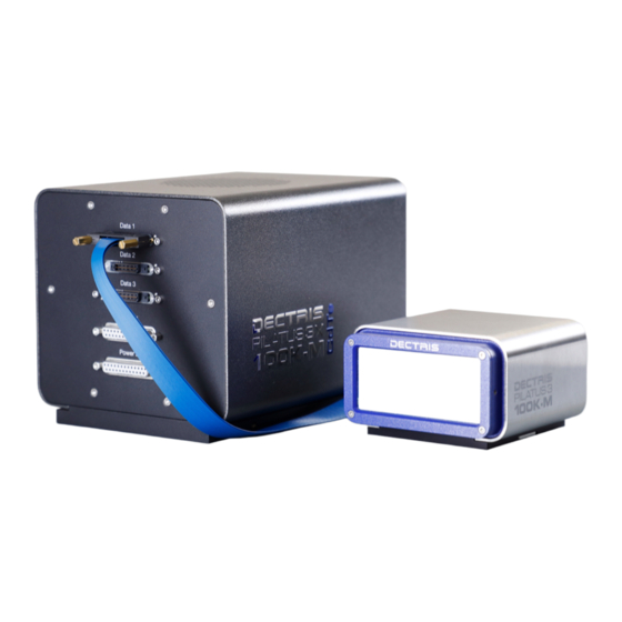
4.1.1. Technical Drawing The PILATUS3 R CdTe 100K-M detector consists of the detector head (figure 4.1) and the detector electronics unit (fig- ure 4.2). For in-vacuum applications electrical and cooling vacuum feedthrough sets (figure 4.3 and figure 4.4) are optionally available. - Page 15 121400.M.80.L10 Electronics for P3 K-Systems Rev. Date of issue Sheet 13.01.2017 1 /1 Figure 4.2: Drawing of the PILATUS3 R CdTe 100K-M Detector electronics unit (also printed separately in the user documentation folder) PILATUS3 R CdTe 100K-M Technical Specifications v1.0.0 10 | 29...
- Page 16 Format F:\Products\SEC02\21\218\F:\Products\SEC02\21\218\ Figure 4.3: Drawing of the optional PILATUS3 R CdTe 100K-M electrical vacuum feedthrough. Please note, that this drawing does not show the adapter boards for the data cables. Figure 4.4: Drawing of the optional PILATUS3 R CdTe 100K-M cooling vacuum feedthrough.
-
Page 17: Detector Head
(figure 4.6). The sensors are behind a 12 µm thick Mylar (PET) foil coated with aluminium to protect them from humidity, dust and from being touched. Figure 4.5: The PILATUS3 R CdTe 100K-M detector head with the protective cover in place (front view) Danger ®... -
Page 18: Detector Electronics Unit
(section 5.4). Pipe: Use a pipe with outer diameter of 4 mm. Coolant inlet. Coolant outlet. 4.1.3. Detector Electronics Unit Figure 4.8: The PILATUS3 R CdTe 100K-M detector electronics unit viewed from the front (left) and back (right). PILATUS3 R CdTe 100K-M Technical Specifications v1.0.0 13 | 29... - Page 19 Although the detector might be already grounded via the mounting bolts, the detector should be grounded additionally via the functional ground connector at the back to establish a defined grounding. FUSE 4 AT Fuse (see table 3.3) PILATUS3 R CdTe 100K-M Technical Specifications v1.0.0 14 | 29...
-
Page 20: Vacuum Feedthroughs (Optional)
The cable of the feedthrough set should not be combined with the default cables of the detector system. Figure 4.9: Picture of the optional PILATUS3 R CdTe 100K-M electrical vacuum feedthrough viewed from the vacuum (left) and air side (right). -
Page 21: Detector Control Unit
Windows Explorer address bar. 4.3. Thermal Stabilization Unit A thermal stabilization unit is required for the operation of the PILATUS3 R CdTe 100K-M detector system. The hoses and the detector are equipped with self-sealing valves to avoid dripping when connecting or disconnecting the tubes. -
Page 22: In-Vacuum Operation For Detectors With Optional Vacuum Compatibility)
Prior to powering up and operating the detector in-vacuum the thermal stabilization unit has to be set to a temperature ◦ of 15 C for at least 30 min. Max.Operating Pressure 2 bar PILATUS3 R CdTe 100K-M Technical Specifications v1.0.0 17 | 29... -
Page 23: Installing The Detector System Transport Considerations
The detector can be mounted in the ways which are described below. 5.2.1. Mounting the Detector Head Figure 5.1: Picture of the PILATUS3 R CdTe 100K-M detector head with extended mounting brackets viewed from below (left) and front (right). Mounting the Detector Head from Above Use the mounting brackets as depicted in figure 5.2. - Page 24 The detector should be mounted using the two internal M6x1 threads as shown in figure 5.3 (indicated with yellow circles). Figure 5.3: Drawing of the PILATUS3 R CdTe 100K-M detector head base plate (a printed copy is supplied in the user documentation folder).
-
Page 25: Mounting The Detector Electronics Unit
The detector electronics unit can be mounted from below using the four internal threads (M6x1). To mount the detector electronics unit from above, optional mounting brackets are available upon request. Figure 5.4: Drawing of the base plate of the PILATUS3 R CdTe 100K-M detector electronics unit (a printed copy is supplied in the user documentation folder). -
Page 26: In-Vacuum Use For Detectors With Optional Vacuum Compatibility
5.5. Connection to Thermal Stabilization Unit The PILATUS3 R CdTe 100K-M detector is water-cooled and must be connected to a dedicated thermal stabilization unit. Use only the provided thermal stabilization unit. -
Page 27: Mounting The Detector Control Unit
Figure 5.6: Examples of cooling connections for operation in vacuum. Depicted are horizontal (left) and vertical (right) connectors from the optional PILATUS3 R CdTe 100K-M cooling vacuum feedthrough set (section 4.1.4). 5.6. Mounting the Detector Control Unit Caution Make sure that the detector control unit has adequate ventilation. -
Page 28: Temperature And Humidity Control
6. TEMPERATURE AND HUMIDITY CONTROL The PILATUS3 R CdTe 100K-M detector has a combined temperature and humidity sensor. The temperature and humidity control shuts down the detector when the humidity or the temperature of the sensor exceeds the following limits in table 6.1. -
Page 29: Operation Procedure
• Turn OFF the detector control unit. • Do not remove the nitrogen/dry air connection. It is a requirement that it is left at the recommended flow rate according to section 5.4. PILATUS3 R CdTe 100K-M Technical Specifications v1.0.0 24 | 29... -
Page 30: Vacuum Operation For Detectors With Optional Vacuum Compatibility
• Check the humidity and change the drying agent frequently for compliance with the storage requirements in section 3.3. 7.6. Cleaning and Maintenance Caution ® The Mylar foil must not be touched or cleaned. If it becomes dirty or is damaged, please contact DECTRIS technical support. PILATUS3 R CdTe 100K-M Technical Specifications v1.0.0 25 | 29... -
Page 31: Safety Instructions Cadmium Telluride
Please refer to the user documentation of the thermal stabilization unit for detailed information about the maintenance of your thermal stabilization unit. The PILATUS3 R CdTe 100K-M detector does not require any maintenance. 7.7. Safety Instructions Cadmium Telluride The sensor material is built up from Cadmium Telluride (CdTe). In order to prevent injuries, please follow these safety pre- cautions: •... -
Page 32: Troubleshooting
Ambient humidity around the detector Shut down the detector immediately exceeds the operating conditions. and check the humidity. Power up the detector only when the ambient hu- midity has been reduced. PILATUS3 R CdTe 100K-M Technical Specifications v1.0.0 27 | 29... -
Page 33: Certification Tests
9. CERTIFICATION TESTS The product is in confirmation with the following standards: Table 9.1: Certification Tests for PILATUS3 R CdTe 100K-M EN 61000-6-2:2016 / IEC 61000-6-2:2005 (ed2.0), (industrial) EN 61000-6-4:2007 + A1:2011 / IEC 61000-6-4:2011 (ed2.1), (industrial) EN 61010-1:2010 / IEC 61010-1:2010 + AMD1:2016 EN 61326-1:2013 / IEC 61326-1:2012 (ed2.0) -
Page 34: Service Form
10. SERVICE FORM PILATUS3 R CdTe 100K-M Technical Specifications v1.0.0 29 | 29...
Need help?
Do you have a question about the PILATUS3 R CdTe 100K-M and is the answer not in the manual?
Questions and answers