Table of Contents

Related Manuals for Moxa Technologies EtherFire IEF-G9010-2MGSFP Series

Summary of Contents for Moxa Technologies EtherFire IEF-G9010-2MGSFP Series
- Page 1 IEF-G9010-2MGSFP Series Quick Installation Guide EtherFire Family Version 2.1, February 2021 Technical Support Contact Information www.moxa.com/support 2021 Moxa Inc. All rights reserved. P/N: 1802090100012 *1802090100012*...
-
Page 2: Package Checklist
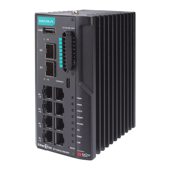
Package Checklist The IEF-G9010-2MGSFP Series, which is an industrial IPS firewall, is shipped with the items listed below. If any of these items are missing or damaged, please contact your customer service representative for assistance. • 1 Industrial next-generation Firewall •... - Page 3 Panel Views of IEF-G9010-2MGSFP Series Front Panel Front Panel: 1. USB port for ABC-02-USB 2. 1000 Mbps SFP port speed LED indicator 3. 1000 Mbps SFP ports 4. 1000 Mbps SFP port speed LED indicator 5. 1000 Mbps copper port speed LED indicator 6.
-
Page 4: Mounting Dimensions
Mounting Dimensions DIN-rail Mounting In the package, the metal DIN-rail mounting kit is fixed to the back panel of the IEF-G9010-2MGSFP Series. Mount the IEF-G9010-2MGSFP Series on the corrosion-free mounting rail that adheres to the EN 60715 standard. - 4 -... -
Page 5: Wall Mounting
Suggested Installation Method STEP 1: Insert the upper lip of the DIN-rail kit into the mounting rail. STEP 2: Press the IEF-G9010-2MGSFP Series towards the mounting rail until it snaps into place. Suggested Removal Method STEP 1: Pull down the latch on the DIN-rail kit with a screwdriver. -
Page 6: Wiring Requirements
STEP 2: Mounting the IEF-G9010-2MGSFP Series on the wall requires four M3 screws. Use the IEF-G9010-2MGSFP Series with the wall mount plates attached as a guide to mark the correct location of the four screws. The wall-mounting holes are marked A in the above diagram. Wiring Requirements WARNING Do not disconnect modules or wires unless power has been... -
Page 7: Wiring The Relay Contact
WARNING Hot Surface. Do not touch. ATTENTION The SFP module only supports Laser Class 1 optical transceivers. Grounding the IEF-G9010-2MGSFP Series Grounding and wire routing help limit the effects of noise due to electromagnetic interference (EMI). Run the ground connection from the ground screw (M4 type) to the grounding surface prior to connecting devices. -
Page 8: Communication Connections
STEP 1: Use a small flat-blade screwdriver to press a wire locker. Top View STEP 2: Insert a positive/negative DC wire into V+/V- terminals respectively. STEP 3: Release the wire locker, and check whether the wire is fixed. Right View The power cord adapter should be connected to a socket outlet with an earthing connection. -
Page 9: The Reset Button
PIN Definition Description A5, B5 A6, B6 A7, B7 10/100/1000BaseT(X) Ethernet Port Connection The 10/100/1000BaseT(X) ports located on the IEF-G9010-2MGSFP Series front panel are used to connect to Ethernet-enabled devices. Most users will choose to configure these ports for Auto MDI/MDI-X mode, in which case the port’s pinouts are adjusted automatically depending on the type of Ethernet cable used (straight-through or cross-over), and the type of device (NIC-type or HUB/Switch-type) connected to the port. -
Page 10: Led Indicators
LED Indicators The front panel of the IEF-G9010-2MGSFP Series has several LED indicators. The function of each LED is described in the following table: Color State Description Power is being supplied to power input P1 on the main module. PWR1 Amber Power is NOT being supplied to power input P1 on the main module. -
Page 11: Specifications
Specifications Input Current 1.265 A @ 12 V 0.605 A @ 24 V 0.308 A @ 48 V Input Voltage 12/24/48 VDC, dual power input Power Consumption 15.18 W (max.) Operating Temperature -10 to 60°C (14 to 140°F), standard models -40 to 75°C (-40 to 185°F), wide-temp.
Need help?
Do you have a question about the EtherFire IEF-G9010-2MGSFP Series and is the answer not in the manual?
Questions and answers