
Subscribe to Our Youtube Channel
Summary of Contents for CTI-CRYOGENICS CRYO-TORR 4F
- Page 1 CR Y OGE NIC S HELIX TECHNOLOGY CORPORATION ® Cryo-Torr High-Vacuum Pump Installation, Operation and Maintenance Instructions 8040613 Rev. A (4/2001) HELIX TECHNOLOGY CORPORATION http://www.helixtechnology.com...
- Page 2 The following Helix Technology Corporation trademarks and service marks may appear in this document: Conductron™ ® ® ® Convectron Cryodyne Cryogen ® ® ® FastRegen™ Cryogenerator Cryo-Torr CTI-Cryogenics Granville-Phillips™ ® Helix Technology.. Your GOLDLink GUTS Vacuum Connection ® ® Mini-Ion™ ® Helix Micro-Ion On-Board ®...
-
Page 3: Table Of Contents
CR Y OGE NIC S Cryo-Torr High-Vacuum Pump Installation, Operation and Maintenance Instructions HELIX TECHNOLOGY CORPORATION Table of Contents Section 1 - Cryo-Torr Cryopump Description Introduction ............1-1 Installation, Operation, and Service Instructions . - Page 4 Tables Table 1-1: Cryo-Torr 4F Cropump Specifications ..... . 1-4 Table 1-2: Cryo-Torr 8 Cryopump Specifications ..... . . 1-5 Table 1-3: Cryo-Torr 8F Cryopump Specifications .
-
Page 5: Section 1 - Cryo-Torr Cryopump Description
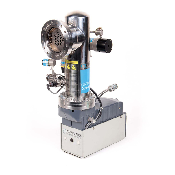
CR Y OGE NIC S Cryo-Torr High-Vacuum Pump Installation, Operation and Maintenance Instructions HELIX TECHNOLOGY CORPORATION Section 1 - Cryo-Torr Cryopump Description Introduction Cryo-Torr High-Vacuum Pumps, shown in Figures 1-1 and 1-2, are one of the two major components that make up the Cryo-Torr High-Vacuum Pumping System. -
Page 6: Figure 1-1: Cryo-Torr High-Vacuum Pumps
CR Y OGE NIC S Cryo-Torr Cryopump Description HELIX TECHNOLOGY CORPORATION CRYO-TORR 8 CRYO-TORR 4F CRYO-TORR 8F CRYO-TORR 10 Figure 1-1: Cryo-Torr High-Vacuum Pumps P/N 8040613... -
Page 7: Figure 1-2: Cryo-Torr High-Vacuum Pumps
CR Y OGE NIC S Cryo-Torr High-Vacuum Pump Installation, Operation and Maintenance Instructions HELIX TECHNOLOGY CORPORATION CRYO-TORR 100 CRYO-TORR 250F CRYO-TORR 500 CRYO-TORR 400 Figure 1-2: Cryo-Torr High-Vacuum Pumps P/N 8040613... -
Page 8: Specifications
CR Y OGE NIC S Cryo-Torr Cryopump Description HELIX TECHNOLOGY CORPORATION Specifications Table 1-1: Cryo-Torr 4F Cropump Specifications Parameter Specifications Rough Pump Connection NW 25 ISO KF Integrated Hardware Second Stage Diode Pumping Speeds: Water 1100 liters/sec 370 liters/sec Hydrogen... -
Page 9: Table 1-2: Cryo-Torr 8 Cryopump Specifications
CR Y OGE NIC S Cryo-Torr High-Vacuum Pump Installation, Operation and Maintenance Instructions HELIX TECHNOLOGY CORPORATION Table 1-2: Cryo-Torr 8 Cryopump Specifications Parameter Specifications Rough Pump Connection NW 25 ISO KF Integrated Hardware Second Stage Diode Pumping Speeds: Water 4000 liters/sec 1500 liters/sec Hydrogen 2500 liters/sec... -
Page 10: Table 1-3: Cryo-Torr 8F Cryopump Specifications
CR Y OGE NIC S Cryo-Torr Cryopump Description HELIX TECHNOLOGY CORPORATION Table 1-3: Cryo-Torr 8F Cryopump Specifications Parameter Specifications Rough Pump Connection NW 25 ISO KF Integrated Hardware Second Stage Diode Pumping Speeds: Water 4000 liters/sec 1500 liters/sec Hydrogen 2200 liters/sec Argon 1200 liters/sec Argon Throughput... -
Page 11: Table 1-4: Cryo-Torr 10 Cryopump Specifications
CR Y OGE NIC S Cryo-Torr High-Vacuum Pump Installation, Operation and Maintenance Instructions HELIX TECHNOLOGY CORPORATION Table 1-4: Cryo-Torr 10 Cryopump Specifications Parameter Specifications Rough Pump Connection NW 25 ISO KF Integrated Hardware Second Stage Diode Pumping Speeds: Water 9000 liters/sec 3000 liters/sec Hydrogen 5000 liters/sec... -
Page 12: Table 1-5: Cryo-Torr 100 Cryopump Specifications
CR Y OGE NIC S Cryo-Torr Cryopump Description HELIX TECHNOLOGY CORPORATION Table 1-5: Cryo-Torr 100 Cryopump Specifications Parameter Specifications Rough Pump Connection NW 25 ISO KF Integrated Hardware Second Stage Diode Pumping Speeds: Water 1100 liters/sec 350 liters/sec Hydrogen 480 liters/sec Argon 285 liters/sec Argon Throughput... -
Page 13: Table 1-6: Cryo-Torr 250F Cryopump Specifications
CR Y OGE NIC S Cryo-Torr High-Vacuum Pump Installation, Operation and Maintenance Instructions HELIX TECHNOLOGY CORPORATION Table 1-6: Cryo-Torr 250F Cryopump Specifications Parameter Specifications Rough Pump Connection NW 25 ISO KF Integrated Hardware Second Stage Diode Pumping Speeds: Water 9500 liters/sec 4000 liters/sec Hydrogen 6800 liters/sec... -
Page 14: Table 1-7: Cryo-Torr 400 Cryopump Specifications
CR Y OGE NIC S Cryo-Torr Cryopump Description HELIX TECHNOLOGY CORPORATION Table 1-7: Cryo-Torr 400 Cryopump Specifications Parameter Specifications Rough Pump Connection NW 25 ISO KF Integrated Hardware Second Stage Diode Pumping Speeds: Water 16,000 liters/sec 6000 liters/sec Hydrogen 12,000 liters/sec Argon 5000 liters/sec Argon Throughput... -
Page 15: Table 1-8: Cryo-Torr 500 Cryopump Specifications
CR Y OGE NIC S Cryo-Torr High-Vacuum Pump Installation, Operation and Maintenance Instructions HELIX TECHNOLOGY CORPORATION Table 1-8: Cryo-Torr 500 Cryopump Specifications Parameter Specifications Rough Pump Connection NW 25 ISO KF Integrated Hardware Second Stage Diode Pumping Speeds: Water 30,000 liters/sec 10,000 liters/sec Hydrogen 10,000 liters/sec... -
Page 16: Theory Of Operation
CR Y OGE NIC S Cryo-Torr Cryopump Description HELIX TECHNOLOGY CORPORATION Theory of Operation Your Cryo-Torr Cryopump consists of a cold head and a vacuum vessel. An 80K condensing array, a 15K array, cold head station heaters, and an 80K radiation shield are located in the vacuum vessel. -
Page 17: Figure 1-3: Cutaway View Of A Typical Cryo-Torr High-Vacuum Pump
CR Y OGE NIC S Cryo-Torr High-Vacuum Pump Installation, Operation and Maintenance Instructions HELIX TECHNOLOGY CORPORATION GAS FLOW FROM USER’S VACUUM SYSTEM INTO INLET OF CRYOPUMP MOUNTING FLANGE 80K CONDENSING ARRAY 15K ARRAY 80K RADIATION SHIELD VACUUM VESSEL COLD HEAD CYLINDER STANDPIPE FILTER Figure 1-3: Cutaway View of a Typical Cryo-Torr High-Vacuum Pump P/N 8040613... -
Page 18: Compressor Gas And Oil Flows
The Cryo-Torr Interface, shown in Figure 1-3, is required when; connecting more than one Cryo-Torr Cryopump to a variety of CTI-CRYOGENICS Compressors, or when connecting a single Cryo-Torr Cryopump to the 9000 Series of compressors. The Cryo-Torr Interface accepts input cryopump power from the compressor and distributes it to a maximum of three Cryo-Torr Cryopumps. -
Page 19: Figure 1-5: Typical Cryo-Torr System With 9000 Series Compressor
CR Y OGE NIC S Cryo-Torr High-Vacuum Pump Installation, Operation and Maintenance Instructions HELIX TECHNOLOGY CORPORATION USER’S VACUUM CHAMBER CRYO-TORR 10 9600 COMPRESSOR CRYOPUMP HELIUM SUPPLY LINE HELIUM RETURN LINE ON-BOARD POWER CABLE CRYO-TORR INTERFACE 208 VAC COOLING WATER Figure 1-5: Typical Cryo-Torr System with 9000 Series Compressor P/N 8040613 1-15... -
Page 20: Figure 1-6: Typical Cryo-Torr System With 8200 Compressor
CR Y OGE NIC S Cryo-Torr Cryopump Description HELIX TECHNOLOGY CORPORATION USER’S VACUUM CHAMBER CRYO-TORR 8F CRYOPUMP 8200 COMPRESSOR HELIUM SUPPLY LINE HELIUM RETURN LINE CRYO-TORR POWER CABLE 208 VAC Figure 1-6: Typical Cryo-Torr System with 8200 Compressor 1-16 P/N 8040613... -
Page 21: Section 2 - Installation
CR Y OGE NIC S Cryo-Torr High-Vacuum Pump Installation, Operation and Maintenance Instructions HELIX TECHNOLOGY CORPORATION Section 2 - Installation Introduction Installation information is presented for experienced and non-experienced Cryo-Torr Cryopump system technicians. The flowchart in Figure 2-1 highlights the major tasks for installation of Cryo-Torr Cryopumps. Refer to Figure 2-1 and the appropriate installation procedure within this section for the type of cryopump being installed. -
Page 22: Vent Pipe Connection
When connecting a vent pipe to your cryopump, the 1.30-inch diameter x 1.38-inch long volume around the relief valve must remain open for proper relief valve operation. Vent pipe adapters are available from CTI-CRYOGENICS (P/N 8080250K008). P/N 8040613... -
Page 23: Roughing Pump Connection
CR Y OGE NIC S Cryo-Torr High-Vacuum Pump Installation, Operation and Maintenance Instructions HELIX TECHNOLOGY CORPORATION Roughing Pump Connection Connect your Cryo-Torr Cryopump to a roughing pump system using a roughing line with the largest inside diameter possible to minimize the roughing time required during start-up procedures prior to normal operation. -
Page 24: Figure 2-2: Gas And Electrical Component Location On A Typical
CR Y OGE NIC S Installation HELIX TECHNOLOGY CORPORATION TEMPERATURE SENSOR PURGE GAS PORT RELIEF VALVE HELIUM GAS SUPPLY FITTING HELIUM GAS RETURN FITTING COLD HEAD ELECTRICAL CONNECTOR Figure 2-2: Gas and Electrical Component Location on a Typical Cryo-Torr Cryopump P/N 8040613... -
Page 25: Helium Return And Supply Line Connections
3. Connect the helium supply line from the supply connector on the cartridge to the gas-supply connector on the Cryo-Torr Cryopump. 4. Attach the supply and return line identification decals (CTI-CRYOGENICS supplied) to their respective connecting pip- ing ends. NOTE: Verify proper helium supply static pressure as described in the Installation Section of the appropriate Compressor Manual. -
Page 26: Crossover Pressure Calculations
CR Y OGE NIC S Installation HELIX TECHNOLOGY CORPORATION Crossover Pressure Calculations Crossover is that point in time when the pumping of a vacuum chamber is switched from rough pumping to high-vacuum pumping. Rough pumping brings the vacuum chamber pressure from one atmosphere (760 torr) down to a pressure of approximately 0.5 torr. -
Page 27: Optimizing Crossover Pressure
CR Y OGE NIC S Cryo-Torr High-Vacuum Pump Installation, Operation and Maintenance Instructions HELIX TECHNOLOGY CORPORATION Optimizing Crossover Pressure The calculated crossover pressure may not be optimized for your system. To help prevent any backstreaming during the roughing of the vacuum chamber, you should stop roughing at as high a pressure as possible. -
Page 28: Crossover Cycle Calculations
CR Y OGE NIC S Installation HELIX TECHNOLOGY CORPORATION Example: For a sputtering application of continuously flowing argon gas at 70 scc/ min, the duration of continuous operation with this gas flow (between regeneration) would be: 16.6 x 2000 (std liters) 474 hours 70 (scc/min) Crossover Cycle Calculations... -
Page 29: Cryopump Start-Up Procedure
CR Y OGE NIC S Cryo-Torr High-Vacuum Pump Installation, Operation and Maintenance Instructions HELIX TECHNOLOGY CORPORATION Cryopump Start-up Procedure 1. Close the Hi-Vac valve to isolate the Cryo-Torr Cryopump. 2. Initiate a Nitrogen purge of the Cryo-Torr Cryopump for one hour. 3. -
Page 30: Cryopump Storage
CR Y OGE NIC S Installation HELIX TECHNOLOGY CORPORATION Cryopump Storage WARNING If the cryopump has been used to pump toxic or dangerous materials, you must take adequate precautions to safeguard personnel. If such a cryopump is shipped to a Product Service Department, clearly mark on all storage cartons the identity of the toxic or dangerous materials to which the cryopump has been subjected. -
Page 31: Section 3 - Regeneration
CR Y OGE NIC S Cryo-Torr High-Vacuum Pump Installation, Operation and Maintenance Instructions HELIX TECHNOLOGY CORPORATION Section 3 - Regeneration Introduction A Cryo-Torr cryopump periodically requires a regeneration cycle to return it to its original operating capabilities. Gases captured from a vacuum chamber and trapped in the cryopump through condensation and cryo-adsorption are held primarily in an ice-like form. -
Page 32: Assisted Regeneration
CR Y OGE NIC S Regeneration HELIX TECHNOLOGY CORPORATION Extended loss of electrical power (10 minutes or longer), system vacuum failure, such as venting with a partially open vacuum isolation valve, and operator error may necessitate cryopump regeneration. NOTE: Short term electrical outages of up to 10 minutes should not result in the need to regenerate your cryopump. - Page 33 CR Y OGE NIC S Cryo-Torr High-Vacuum Pump Installation, Operation and Maintenance Instructions HELIX TECHNOLOGY CORPORATION 5. When the condensing arrays reach ambient temperature, rough the cryopump to an initial starting pressure, usually between 50 and 100 microns. NOTE: After roughing, perform a rate-of-rise (ROR) test to ensure that your cryopump regeneration has been thorough and that no air-to-vacuum leaks are present.
-
Page 34: Section 4 - Troubleshooting
20K, the roughing time to 50µ, the time to base pressure at crossover, the time between regeneration cycles, and the compressor pressure reading. Technical Inquiries Please refer to Appendix A of this manual for a complete list of the CTI-CRYOGENICS’ world wide customer support centers. P/N 8040613... -
Page 35: Table 4-1: Troubleshooting Procedures
CR Y OGE NIC S Troubleshooting HELIX TECHNOLOGY CORPORATION Table 4-1: Troubleshooting Procedures Problem Possible Cause Corrective Action High base pressure of vacuum Air-to-vacuum leak in vac- Check cryopump relief valve system, and a cryopump tem- uum system or in cryopump. for proper seating. - Page 36 CR Y OGE NIC S Cryo-Torr High-Vacuum Pump Installation, Operation and Maintenance Instructions HELIX TECHNOLOGY CORPORATION Table 4-1: Troubleshooting Procedures (Continued) Problem Possible Cause Corrective Action Cryopump fails to cool down Low helium supply pressure. Add gas as described in the to the required operating tem- appropriate Compressor perature or takes too long to...
-
Page 37: Section 5 - Maintenance Procedures
CR Y OGE NIC S Cryo-Torr High-Vacuum Pump Installation, Operation and Maintenance Instructions HELIX TECHNOLOGY CORPORATION Section 5 - Maintenance Procedures Helium Circuit Decontamination Contamination of the helium-gas circuit is indicated by sluggish or intermittent operation (ratchetting) of the cold head drive mechanism. With severe contamination the cold head drive may seize and fail to operate. - Page 38 For best results, CTI-CRYOGENICS suggests a dedicated helium bottle, regulator, and line, which are never separated, for adding helium.
-
Page 39: Cleaning The Cryo-Torr Cryopump
CR Y OGE NIC S Cryo-Torr High-Vacuum Pump Installation, Operation and Maintenance Instructions HELIX TECHNOLOGY CORPORATION c. Perform the flushing steps a and b four more times. d. Pressurize the cold head to a static charge pressure of 195- 205 psig (1345-1415 kPa) and run the cold head drive motor for 10 to 30 seconds. -
Page 40: Table 5-1: Indium Gasket Screw Torque Specifications
CR Y OGE NIC S Maintenance Procedures HELIX TECHNOLOGY CORPORATION b. Rinse the item in clean hot water. c. Air or oven dry all items at 150°F (66°C) maximum before reinstalling into the cryopump. CAUTION Do not clean the 15K cryo-adsorbing array, because you may severely contaminate the adsorbent in the cleaning process. - Page 41 CR Y OGE NIC S Appendix A - Customer Support Centers HELIX TECHNOLOGY CORPORATION Appendix A - Customer Support Centers Introduction Refer to Table A-1 for the nearest Customer Support Center for technical assistance or service. North American customers may call 800-FOR- GUTS (800-367-4887) 24 hours a day, seven days a week.
-
Page 42: Table A-1: Customer Support Centers
CR Y OGE NIC S Appendix A - Customer Support Centers HELIX TECHNOLOGY CORPORATION Table A-1: Customer Support Centers United States and Canada United States and Canada Helix Technology Corporation Helix Technology Corporation Customer Response Center 3350 Montgomery Drive Nine Hampshire Street Santa Clara, California 95054 U.S.A. - Page 43 CR Y OGE NIC S Appendix A - Customer Support Centers HELIX TECHNOLOGY CORPORATION Table A-1: Customer Support Centers (Continued) Germany, Italy, Denmark, Switzerland, France, Spain, Portugal, Greece Holland, Norway, The Netherlands Helix Technology Helix Technology Corporation Domaine Technologique de Saclay Haasstrasse 15 4, rue Rene Razel, Bât Apollo D-64293 Darmstadt...
- Page 44 Table A-1: Customer Support Centers (Continued) China Australia, New Zealand, Tasmania Helix Technology Corporation Helix Technology Corporation Tritek International Company CTI-Cryogenics Products Da An Square, 9A Middle Bldg AVT Services Pte. Ltd. 829 Yan An Middle Road Unit 1, 12 Pioneer Avenue Shanghai, 200040...
- Page 45 Appendix A - Customer Support Centers HELIX TECHNOLOGY CORPORATION Table A-1: Customer Support Centers (Continued) India India Helix Technology Corporation Helix Technology Corporation CTI-Cryogenics Products Granville-Phillips Products Goodwill Cryogenics Enterprise Ashwini Enterprises 213 Nirman, Sec. 17, Vashi C-2/13/03, Sector-16, Vashi New Bombay, 400703...
Need help?
Do you have a question about the CRYO-TORR 4F and is the answer not in the manual?
Questions and answers