
Summary of Contents for USR IOT USR-C215
- Page 1 USR-C215 Hardware Manual www.usriot.com USR-C215 Hardware Manual File version: 1.1.01 Jinan USR IOT Technology Limited 1 / 8 h.usriot.com...
- Page 2 USR-C215 Hardware Manual www.usriot.com Content USR-C215 Hardware Manual ...................... 1 1. Product Overview ........................3 1.1. Dimension ........................3 1.2. Pin Defination ........................ 3 2. Hardware Design ........................5 2.1. Typical Connection ......................5 2.2. Power Interface......................5 2.3. UART Interface ......................6 2.4.
- Page 3 USR-C215 Hardware Manual www.usriot.com 1. Product Overview 1.1. Dimension Module size: 22.0*13.5mmmm, error ± 0.2mm, pin size as follows: Figure 1 Dimension 1.2. Pin Definition Jinan USR IOT Technology Limited 3 / 8 h.usriot.com...
- Page 4 LED nLINK Indication pin for module WIFI linking successfully, take effect in low level and can connect to external LED Figure 2 Pin definition Jinan USR IOT Technology Limited 4 / 8 h.usriot.com...
- Page 5 Switching power supply is recommended. Working voltage VCC range from 3.0V~3.6V, 3.3V is recommended. Power the module by main power pin, pin interface is in parallel with appropriate energy-storage capacitance and high frequency capacitance. Circuit diagram as follows: Figure 4 Power interface Jinan USR IOT Technology Limited 5 / 8 h.usriot.com...
- Page 6 Resetting the module and taking effect in low level. nReset pin connect to internal 100K Ohm pull-up resistor to 3.3V. Press over 0.5s and release to reset the device. Circuit diagram as follows: Figure 6 Reset and Reload Jinan USR IOT Technology Limited 6 / 8 h.usriot.com...
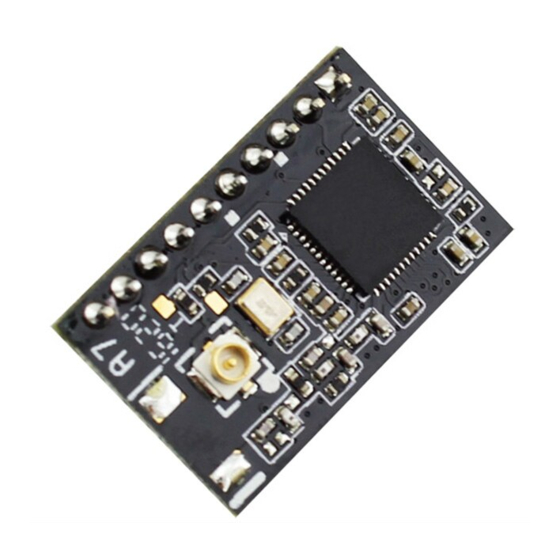
- Page 7 USR-C215 Hardware Manual www.usriot.com 2.5. Antenna USR-C215 have external I-PEX antenna. Note: 1. On PCB board, user can’t place component on antenna part. 2. Keep antenna away from metal, inductance or some other interference source. 3. Ensure antenna locate on margin of PCB board.
- Page 8 4. Disclaimer This document provide the information of USR-C215 products, it hasn’t been granted any intellectual property license by forbidding speak or other ways either explicitly or implicitly. Except the duty declared in sales terms and conditions, we don’t take any other responsibilities. We don’t warrant the products sales and use explicitly or implicitly, including particular purpose merchantability and marketability, the tort liability of any other patent right, copyright, intellectual property right.
Need help?
Do you have a question about the USR-C215 and is the answer not in the manual?
Questions and answers