Table of Contents
Advertisement
Available languages
Available languages
Quick Links
Advertisement
Chapters
Table of Contents

Subscribe to Our Youtube Channel
Related Manuals for Bticino Megabreak 2500


Summary of Contents for Bticino Megabreak 2500
- Page 1 Megabreak® Manuale installatore • Installation manual...
- Page 2 Megabreak® ITALIAN ENGLISH...
-
Page 3: Table Of Contents
Megabreak® Indice 1 Pesi 2 Movimentazione e disimballaggio relativi a interruttori 3 Immagazzinamento di interruttori fissi ed estraibili 4 Identificazione 5 Rimozione del coperchio frontale 6 Componentistica / Parti costitutive 7 Funzionamento / Ciclo di Prova 8 Specifiche tecniche 9 Caratteristiche dei principali accessori elettrici 10 Installazione e taglio della portella 11 Attacchi - Interruttori fissi 12 Attacchi –... -
Page 4: Indice 1 Pesi
152 kg 73 kg 77 kg 108 kg 225 kg Estraibile 90 kg 94 kg 137 kg 274 kg Interruttori sezionatori Tipo Megabreak 2500 Megabreak 4000 Megabreak 6300 Corrente 1250/1600/ nominale 3200/4000 6300 2000/2500 39 kg 57 kg 114 kg... - Page 5 Megabreak® Versione fissa Versione estraibile t=k@1 t=k@1 MEM=O MEM=O 0.08 @6Ir 0.08 @6Ir 0.04 0.04 0.00 0.02 0.02 0.00 I>1.05 I>.90 I>.90 I>1.05 Rimuovere le viti di fissaggio dell’interruttore Versione fissa Versione estraibile Megabreak Megabreak 2500-4000 2500-4000-6300 ar ge t=k@1 MEM= 0.08 @6Ir...
- Page 6 Per facilitare il trasporto, sono disponibili apposite piastre di sollevamento (accessorio opzionale MT809PS) Versione fissa Megabreak 2500-4000 Megabreak 6300 Accessorio opzionale MT809PS Versione estraibile a r g d is t= k@ xI r xI n Ic w xI n 0. 8 0.
- Page 7 Megabreak® Megabreak 2500 Megabreak 2500-4000-6300 Gli interruttori Megabreak 2500-4000 (versione fissa ed estraibile) possono anche essere trasportati da due addetti. Apparecchiatura pesante. Usare la massima cautela onde evitare incidenti e lesioni alle persone e/o danni all’interruttore/attrezzatura. Non sollevare l’interruttore per...
-
Page 8: Immagazzinamento Di Interruttori Fissi Ed Estraibili
MEM= ha rg 0.08 @6Ir di sc 0.04 12Ir 0.02 t=k@ 0.00 I>.90 MEM= I>1.05 0.08 @6Ir 0.04 0.02 0.00 I>.90 I>1.0 Versione fissa Versione estraibile Megabreak 2500-4000-6300 Non impilare più di 2 interruttori Max 2 uno sopra l’altro. -
Page 9: Identificazione
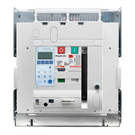
Megabreak® 4. Identificazione Indicatore di stato dei contatti principali Indicatore stato delle molle Tasto di reset del dispositivo di sgancio 4a Codice articolo identificativo del prodotto 4b Famiglia di prodotto 4c Categoria di utilizzo 4d Standard di conformità 4e Potere di interruzione di servizio in corto circuito 4f Corrente nominale ammissibile di breve durata... -
Page 10: Rimozione Del Coperchio Frontale
5. Rimozione del Per interruttori fissi ed estraibili. coperchio frontale 4 /S 4 /S r g e c h a d is 12 Ir r g e c h a d is 12 Ir @ 6Ir xI r I> I> xI r I>... -
Page 11: Componentistica/Parti Costitutive
Megabreak® 6. Componentistica/ Parti costitutive Versione fissa Unità di protezione Contatti di stato Tasto di reset Tasto OFF Tasto ON Indicatore ON-OFF Indicatore stato delle molle Maniglia di carica Cella Dejon 10 Tappo per mini USB 11 Coperchietto batterie 12 Meccanismo di inserimento 13 Inserimento maniglia di inserzione/manovra 14 Scorrevole di consenso per... - Page 12 Morsettiera ausiliari Cella Protezione isolante Versione estraibile Messa a terra automatica Collegamento di terra Cassetto scorrevole...
- Page 13 Megabreak® Soltanto per interruttori estraibili 1 Rimuovere il coperchio frontale. 2 Se necessario installare l'interblocco meccanico. 3 Se necessario installare il contatto pronto a chiudere molle cariche. 4 Se necessario installare il comando a motore. 5 Se necessario installare il blocco a chiave per la versione estraibile (accessorio opzionale). 6 Avvitare la custodia della maniglia di inserzione/manovra al supporto fornito a corredo.
-
Page 14: Funzionamento/Ciclo Di Prova
7. Funzionamento/ Prima di installare l’interruttore, eseguire le seguenti operazioni. Ciclo di Prova Inizialmente, l’interruttore è e le molle sono discharged discharged charged charged discharged discharged discharged discharged a rg d is xI r I>. I>1 a rg d is discharged xI r I>. - Page 15 Megabreak® discharged charged Premere il tasto ‘ON’ per chiudere l’interruttore. Ora, l’interruttore è e le molle sono discharged discharged In tale condizione, le molle possono essere nuovamente caricate per manovre successive. discharged charged discharged discharged a rg d is xI r I>.
-
Page 16: Specifiche Tecniche
8. Specifiche Caratteristiche generali tecniche INTERRUTTORI Megabreak® In conformità con la IEC 60947-2 Megabreak® Megabreak® Megabreak® 2500 2500 4000 6300 Megabreak® 42kA Numero di poli 3P-4P 3P-4P 3P-4P 3P-4P Corrente nominale degli sganciatori In (A) 630÷1600 630÷2500 3200-4000 5000-6300 Tensione nominale di isolamento Ui (V) 1000 1000 1000... - Page 17 Megabreak® SEZIONATORI Megabreak® Megabreak® Megabreak® In conformità con la IEC 60947-3 Megabreak® I 2500 I 4000 I 6300 Numero di poli 3P-4P 3P-4P 3P-4P Corrente nominale degli sganciatori In (A) 1250÷2500 3200-4000 6300 Tensione nominale di isolamento Ui (V) 1000 1000 1000 Tensione nominale tenuta...
- Page 18 Dimensioni reali dell'apparecchio Megabreak Megabreak Megabreak 2500 4000 6300 Dimensioni – versione fissa 3P Larghezza 273 mm 408 mm 797 mm Profondità 354 mm 354 mm 354 mm Altezza 419 mm 419 mm 419 mm Dimensioni – versione fissa 4P Larghezza 358 mm 538 mm...
-
Page 19: Caratteristiche Dei Principali Accessori Elettrici
Potenza massima assorbita (W/VA): 180/180 (Megabreak 2500), 240/240 (Megabreak 4000-6300) Corrente allo spunto: 2÷3xIn (per circa 80ms) Durata della carica (s): 5 (Megabreak 2500), 7 (Megabreak 4000-6300) Frequenza manovre (n°/min): 2 (Megabreak 2500), 1 (Megabreak 4000-6300) Bobina di chiusura Dati tecnici Tensione nominale Vn (Va.c.): 24V-48V-110V÷130V-220V÷250V -415V/440V/480V... - Page 20 Contatti di segnalazione per ausiliari elettrici Dati tecnici Tensione nominale Vn (Va.c.): 250V 16A (Vd.c.): 250V 0,3A Contatti di segnalazione aggiuntivi Dati tecnici Tensione nominale Vn (Va.c.): 250V 16A (Vd.c.): 250V 0,3A Contatto pronto a chiudere molle cariche Dati tecnici Tensione nominale Vn (Va.c.): 250V 16A Contatti inserito/test/estratto Dati tecnici...
-
Page 21: Installazione E Taglio Della Portella
Megabreak® 10. Installazione Tipica installazione di interruttori Megabreak® in un quadro. e taglio della portella ch arg 12Ir t=k@ MEM= 0.08 @6Ir 0.04 0.02 0.00 I>.90 I>1.0 ch arg 12Ir t=k@ MEM= 0.08 @6Ir 0.04 0.00 0.02 I>.90 I>1.0... - Page 22 10.1 Installazione di un interruttore Megabreak® in versione fissa Megabreak 2500. Dettagli per il montaggio (anche per la versione 42kA). BUS BAR BUS BAR = Punto di fissaggio alla piastra del quadro...
- Page 23 Megabreak® Megabreak 4000. Dettagli per il montaggio. BUS BAR BUS BAR = Punto di fissaggio alla piastra del quadro...
- Page 24 Megabreak 6300. Dettagli per il montaggio BUS BAR BUS BAR 1057 = Punto di fissaggio alla piastra del quadro...
- Page 25 Megabreak® 10.2 Taglio della portella per la versione fissa Megabreak 2500-4000-6300. Dettagli per il montaggio. Operazione non necessaria se si dispone ø4 (x10) di un pannello frontale serie MAS * Megabreak 2500 = 11,5 Megabreak 4000 = 56 Megabreak 6300 = 186...
- Page 26 10.3 Installazione dell’interruttore Megabreak® in versione estraibile Megabreak 2500. Dettagli per il montaggio (anche per la versione 42kA). BUS BAR BUS BAR BUS BAR BUS BAR = Punto di fissaggio alla piastra del quadro Megabreak 4000. Dettagli per il montaggio.
- Page 27 Megabreak® Megabreak 6300. Dettagli per il montaggio. BUS BAR BUS BAR 1064 = Punto di fissaggio alla piastra del quadro...
- Page 28 Megabreak 2500-4000-6300. Dettagli per il montaggio. = Punto di fissaggio alla piastra del quadro 95,4 124,7 59,8 89,1 109,4 97,2 126,5 146,8 TEST...
- Page 29 Megabreak® 10.4 Taglio e foratura della portella per la versione estraibile Megabreak 2500-4000-6300. Dettagli per il montaggio. Operazione non ø4 (x10) necessaria se si dispone di un pannello frontale serie MAS * Megabreak 2500 = 16,5 Megabreak 4000 = 66...
- Page 30 10.5 Fissaggio della cornice sulla portella Funzione: assicurare il grado di protezione. Installazione: - fissare la cornice e la gomma sulla portella in modo da far combaciare le forature. - avvitare la cornice dall'interno della portella. 0,5 Nm...
-
Page 31: Attacchi - Interruttori Fissi
Megabreak® 11. Attacchi - Megabreak 2500. 3 poli. Interruttori fissi 45,5 45,5 45,5 45,5 per la versione 42 kA Megabreak 4000. 3 poli. - Page 32 Megabreak 6300. 3 poli.
- Page 33 Megabreak® Megabreak 2500. 4 poli. 45,5 45,5 45,5 45,5 per la versione 42 kA Megabreak 4000. 4 poli.
- Page 34 Megabreak 6300. 4 poli.
-
Page 35: Attacchi - Interruttori Estraibili
Megabreak® 12. Attacchi – Megabreak 2500. 3 poli. Attacchi piatti. Interruttori estraibili 116,5 116,5 41,5 116,5 116,5 41,5 116,5 116,5 41,5 per la versione 42 kA Attacchi orizzontali. ø11 ø11 ø11 85,5 85,5 116,5 116,5 41,5 116,5 116,5 41,5 85,5... - Page 36 Megabreak 4000. 3 poli. Attacchi piatti. Attacchi orizzontali. ø11 ø11 ø11 86,5 86,5 86,5 Attacchi verticali. ø11 ø11 ø11 86,5 86,5 86,5...
- Page 37 Megabreak® Megabreak 6300. 3 poli. Attacchi piatti. Attacchi orizzontali. ø11 ø11 ø11 86,5 86,5 86,5 Attacchi verticali. ø11 ø11 ø11 86,5 86,5 86,5...
- Page 38 Megabreak 2500. 4 poli. Attacchi piatti. 85 85 106 106 41,5 85 85 106 106 41,5 85 85 106 106 41,5 per la versione 42 kA Attacchi orizzontali. ø11 ø11 ø11 41,5 85 73 85,5 41,5 85 73 41,5 85 73...
- Page 39 Megabreak® Megabreak 4000. 4 poli. Attacchi piatti. Attacchi orizzontali. ø11 ø11 ø11 86,5 86,5 130 77 130 77 86,5 130 77 Attacchi verticali. ø11 ø11 ø11 86,5 86,5 86,5...
- Page 40 Megabreak 6300. 4 poli. Attacchi piatti. 1064 1064 1064 Attacchi orizzontali. ø11 ø11 ø11 86,5 86,5 86,5 1064 1064 1064 Attacchi verticali. ø11 ø11 ø11 86,5 86,5 86,5 1064 1064 1064...
-
Page 41: Connessione Di Un Interruttore In Esecuzione Fissa
Megabreak® 13. Connessione Megabreak 2500. di un interruttore in esecuzione fissa Icc (kA) ≤ 42 ≤ 50 ≤ 65 ≤ 100 “X” max (mm) Il supporto delle barre deve essere di materiale isolante e opportunamente dimensionato per non compromettere le... - Page 42 Megabreak 4000. Icc (kA) ≤ 42 ≤ 50 ≤ 65 ≤ 100 Il supporto delle barre deve “X” max (mm) essere di materiale isolante e opportunamente dimensionato per non compromettere le prestazioni in presenza di un eventuale cortocircuito 11mm "X" max (mm) "X"...
- Page 43 Megabreak® Megabreak 6300. Icc (kA) ≤ 42 ≤ 50 ≤ 65 ≤ 100 Il supporto delle barre deve “X” max (mm) essere di materiale isolante e opportunamente dimensionato per non compromettere le prestazioni in presenza di un eventuale cortocircuito 11mm "X"...
-
Page 44: Possibile Connessione Di Un Interruttore In Esecuzione Estraibile
14. Possibile Gli attacchi posteriori degli interruttori Megabreak® offrono una maggiore area di contatto al fine di accettare collegamenti in alluminio. connessione di Gli attacchi piatti universali dei Megabreak® agevolano notevolmente le operazioni di collegamento. un interruttore Tali attacchi supportano e accettano direttamente tutti i tipi di connessione comunemente utilizzati, come mostrato nella figura sottostante. - Page 45 Installazione dell’attacco posteriore orientabile, disponibile come accessorio. Il supporto delle barre deve essere di materiale isolante e opportunamente dimensionato per non compromettere le Megabreak 2500 = 25 Nm prestazioni in presenza di un Megabreak 4000 = 36 Nm eventuale cortocircuito Megabreak 6300 = 36 Nm Icc (kA) ≤...
-
Page 46: Collegamento Della Terra
15. Collegamento Per effettuare il collegamento di messa a terra, utilizzare i fori indicati, fissando il capocorda con il dado M10 dato a corredo con l’interruttore. della terra Versione fissa 36 Nm Versione estraibile 36 Nm... -
Page 47: Inserimento E Montaggio Nel Quadro
Per facilitare la movimentazione dell’interruttore, sono disponibili apposite piastre di sollevamento (accessorio opzionale MT809PS). Soltanto gli interruttori ‘Megabreak 2500’ possono essere trasportati anche da due addetti. Assicurarsi che l’interruttore venga posizionato precisamente nelle 2 sedi poste su entrambi i lati del cassetto. - Page 48 Spingere delicatamente l’interruttore nella posizione di ‘estratto’ e chiudere la portella. Qualora si disponga dell’accessorio “blocco di taglia” (accessorio opzionale MT806AT), è importante sapere che la cella non accetterà interruttori con correnti nominali differenti rispetto a quelle previste. rg ed di sc 12Ir t=k@...
-
Page 49: Blocco Terminali Ausiliari
Megabreak® 17. Blocco terminali ausiliari... - Page 50 17.1 Sganciatore di apertura a lancio di corrente (‘ST’) Permette di aprire l’interruttore con un segnale elettrico. In base alle caratteristiche del dispositivo, è sempre possibile aprire l’interruttore (quando chiuso). A seconda della tipologia, lo sganciatore di apertura funziona sia su corrente alternata che continua. Questo sistema può...
-
Page 51: Nuovo Sistema Di Cablaggio
Megabreak® 18. Nuovo sistema Nuovo sistema automatico "Cage Clamps" (morsetti plug in). La pressione costante sui cavi garantisce il contatto ottimale nel tempo. Il problema del 1/2 di giro sui di cablaggio morsetti a vite risulta così definitivamente risolto. La forma arrotondata della molla evita gli inconvenienti relativi all’incisione dei morsetti. 1. - Page 52 Porta Seriale Supervisione - RS485 (–) H15: Uscita Selettività Logica Porta Seriale Supervisione - RS485 (+) H16: Uscita Selettività Logica Versione base (solo per Megabreak 2500 42kA) M8TA W) Relè programmabile locale (4A-230V a.c. max) W1: Normalmente Aperto W2: Normalmente Chiuso...
-
Page 53: Schema Elettrico
Megabreak® 19. Schema 3 poli (3P+Next) elettrico... - Page 54 4 poli...
- Page 55 Megabreak® 3 poli...
- Page 56 4 poli...
-
Page 57: Test Dielettrico (Ove Disponibile)
Megabreak® 20. Test dielettrico Prima di effettuare un test dielettrico sull’interruttore, che sia solo o installato in un determinato quadro, è obbligatorio ruotare il selettore dalla posizione di “normale utilizzo” a quella di “test (se presente) dielettrico”. Al termine del suddetto test, riposizionare il selettore su “normale utilizzo”. I T I O L E C D I E... -
Page 58: Impostazione Dell'unità Di Protezione
21. Impostazione 21.1 Inserimento/sostituzione delle batterie dell’unità Rimuovere il coperchio frontale dell’interruttore. Inserire le 4 batterie nella parte inferiore dell’unità di protezione, mantenendo polarità e sequenza di montaggio indicate in figura (al primo di protezione inserimento il kit batterie viene fornito a corredo in un apposito sacchetto). A fine vita, smaltire batterie incluse... - Page 59 Megabreak® 21.4 Sigillo dell’unità di protezione Controllare le impostazioni attraverso il display. Richiudere lo sportellino dell’unità di protezione e sigillare l’unità di protezione per mezzo di una normale piombatura. a r g d is t= k@ xI r xI n 6I r Ic w xI n...
-
Page 60: Funzioni Standard Dell'interruttore
22. Funzioni 22.1 Tasto di reset standard Posizione MAN (manuale). dell’interruttore Si tratta dell’impostazione di fabbrica che il cliente trova sul nuovo prodotto acquistato. Mediante il selettore, può essere inibita la chiusura dell’interruttore dopo un intervento di sgancio da parte del dispositivo di protezione. Nel caso in cui si imposti tale funzione, l’operatore dovrà premere tasto prima di poter eseguire ancora la manovra di chiusura. - Page 61 Megabreak® 22.1.1 Contatto di scattato relè Il funzionamento del contatto di scattato ("CTR" nella morsettiera ausiliari elettrici) dipende dal settaggio del pulsante dei reset (AUT/MAN), come mostrato nella prossima immagine. C TR a rg d is I P ! xI r I>.
-
Page 62: Messa In Servizio
23. Messa Verifiche a carico dell’operatore in servizio Prima di procedere alla messa in servizio dell’apparecchio è necessario verificare da parte dell’operatore delegato, che l’apparecchio all’interno del quadro elettrico sia stato correttamente installato e non ci siano condizioni d’installazione non corrette o errori dati da negligenza e l’eventuale presenza di oggetti estranei alla stessa , verificando il rispetto delle normative vigenti. - Page 63 Megabreak® a rg d is a r g d i s xI r t= k I>. I>1 0 .2 0 .3 0 .3 0 .0 x Ir discharged r g e 0 .1 0 .0 6 Ir x In c h a Ic w d i s 0 .0...
- Page 64 Verifiche sotto tensione: Le verifiche dielettriche devono essere condotte sul quadro in accordo alle norme internazionali e condotte da personale specializzato e qualificato con apparecchiature idonee. Per poter eseguire correttamente le verifiche è obbligatorio rispettare le seguenti prescrizioni, nel pieno rispetto delle indicazioni contenute nel manuale di utilizzo del apparecchio al fine di prevenire danni all’apparecchiatura e a persone.
- Page 65 Megabreak® Una volta accertata la natura del guasto, prima della messa in servizio dell’apparecchio, si consiglia di effettuare delle verifiche sull’apparecchio , in modo particolare, verificare le condizioni d’isolamento e dielettriche su una parte o sull’intera installazione in funzione dell’evento. Queste verifiche e le modalità...
-
Page 66: Manutenzione Ordinaria
24. Manutenzione ordinaria a rg a rg d is d is xI r xI r I>. I>1 I>. I>1 discharged Una manutenzione ordinaria, eseguita con la giusta frequenza, è importante al fine di: - controllare e mantenere l'efficienza dell'interruttore; - individuare parti/accessori danneggiati; - prevenire eventuali emergenze. -
Page 67: Risoluzione Dei Problemi Base
Megabreak® 25. Risoluzione PROBLEMA PROBABILE CAUSA RIMEDIO dei problemi base Selettore per il test dielettrico Posizionare il selettore in posizione “dielectric test” in posizione “normal use” Lo sganciatore di minima Alimentare la bobina tensione è presente di minima tensione ma non è alimentato Caricare manualmente le Le molle del meccanismo molle del meccanismo, finché... - Page 69 Megabreak® Manuale installatore • Installation manual...
- Page 71 Megabreak® Contents 1 Weights 2 Handling and unpacking 3 Storage for fixed and draw-out breakers 4 Identification 5 Racking-out frontal cover 6 Exploring 7 Operating 8 Tecnical specifications 9 Features of the main electrical accessories 10 Installation and door cut-out 11 Termination - Fixed Breakers 12 Termination - Draw-out breakers 13 Connection for fixed version...
-
Page 72: Weights
152 kg 73 kg 77 kg 108 kg 225 kg Draw-out 90 kg 94 kg 137 kg 274 kg Switch disconnectors Type Megabreak 2500 Megabreak 4000 Megabreak 6300 1250/1600/ Rating (A) 3200/4000 6300 2000/2500 39 kg 57 kg 114 kg Fixed... - Page 73 @6Ir 0.04 0.00 0.02 0.02 0.04 0.00 I>.90 I>1.05 I>1.05 I>.90 Remove breaker mounting screws. Fixed version Draw-out version Megabreak 2500-4000 Megabreak 2500-4000-6300 ar ge t=k@1 MEM= 0.08 @6Ir 0.04 0.02 0.00 I>.90 I>1.05 Only for fixed version Megabreak 6300...
- Page 74 A special lifting handle are available (optional MT809PS) to facilitate handling. Fixed version Megabreak 2500-4000 Megabreak 6300 MT809PS Optional Draw-out version a r g d is t= k@ xI r xI n Ic w xI n 0. 9 0. 8 0.
- Page 75 Megabreak® Megabreak 2500 Megabreak 2500-4000-6300 Megabreak 2500-4000 breakers (fixed and draw-out version) can also be transported by 2 persons. Heavy equipment. Exercise proper care to avoid personal injury and equipment damage. Do not lift the breaker using front face or Terminals.
-
Page 76: Storage For Fixed And Draw-Out Breakers
0.08 @6Ir di sc 0.04 12Ir 0.02 t=k@ 0.00 I>.90 MEM= I>1.05 0.08 @6Ir 0.04 0.02 0.00 I>.90 I>1.0 Fixed version Draw-out version Megabreak 2500-4000-6300 Do not stack more than 2 Max 2 breakers one above the other. -
Page 77: Identification
Megabreak® 4. Identification Main contacts status indication Spring status indication Reset button for tripping device 4a Product reference 4b Product type 4c Utilization Category 4d Standards compliance 4e Rated service short-circuit breaking capacity 4f Rated short-time withstand current 4g Rated Current Fixed version 4h Rated insulation voltage 4i Rated impulse withstand... -
Page 78: Racking-Out Frontal Cover
5. Racking-out For fix and draw-out breakers. frontal cover 4 /S 4 /S r g e c h a d is 12 Ir r g e c h a d is 12 Ir xI r I> I> xI r I> I>... -
Page 79: Exploring
Megabreak® 6. Exploring Protection Unit Auxiliary Contacts Reset button Fixed version OFF button ON button ON-OFF Indication Spring Status Indication Charging handle Dejon cell cover 10 Mini USB cover 11 Battery cover 12 Draw-out mechanish 13 Draw-out bar insertion 14 Racking shutter 15 Support to place the breaker in draw-out cassette 16 Draw-out main shaft... - Page 80 Aux terminal block Base Safety shutter Draw-out version Megabreak automatic Breaker Earth connection Earth terminal Removable cassette...
- Page 81 Megabreak® Only for draw-out breaker 1 Remove frontal cover 2 If necessary install the mechanical interlock 3 If necessary install the ready to close contact 4 If necessary install the motor operator 5 If necessary install the keylock (optional) for draw-out version 6 Screw the case of the draw-out bar on the delivered support 1 Nm 1 Nm...
-
Page 82: Operating
7. Operating Before installing the breaker, follow the following operations. Initially, the Breaker is and Spring is discharged discharged charged charged discharged discharged discharged discharged a rg d is xI r I>. I>1 a rg d is discharged xI r I>. - Page 83 Megabreak® discharged charged Push ‘ON’ button to close the breaker. Now, the breaker is and spring is discharged discharged In this situation, spring can be charged again for next operation. discharged charged discharged discharged a rg d is xI r I>.
-
Page 84: Tecnical Specifications
8. Tecnical General features specifications CIRCUIT BREAKERS Megabreak® According to IEC 60947-2 Megabreak® Megabreak® Megabreak® 2500 2500 4000 6300 Megabreak® 42kA Poles number 3P-4P 3P-4P 3P-4P 3P-4P Rated uninterrupted current (In) [A] 630÷1600 630÷2500 3200-4000 5000-6300 Isolation voltage (Ui) [V] 1000 1000 1000... - Page 85 Megabreak® SWITCH DISCONNECTORS Megabreak® Megabreak® Megabreak® According to IEC 60947-3 Megabreak® I 2500 I 4000 I 6300 Poles number 3P-4P 3P-4P 3P-4P Rated uninterrupted current (In) [A] 1250÷2500 3200-4000 6300 Isolation voltage (Ui) [V] 1000 1000 1000 Rated impulsive voltage (Uimp) [kV] Service voltage at 50÷60Hz (Ue) [V] Utilization category AC23...
- Page 86 152 kg 73 kg 77 kg 108 kg 225 kg Draw-out 90 kg 94 kg 137 kg 274 kg SWITCH DISCONNECTORS Type Megabreak 2500 Megabreak 4000 Megabreak 6300 1250/1600/ Rating (A) 3200/4000 6300 2000/2500 39 kg 57 kg 114 kg Fixed...
-
Page 87: Features Of The Main Electrical Accessories
Voltage range (% Vn): 85÷110 Maximum power consumption (W/VA): 180/180 (Megabreak 2500), 240/240 (Megabreak 4000-6300) Maximum peak current for about 80ms: 2÷3xIn Charging time (s): 5 (Megabreak 2500), 7 (Megabreak 4000-6300) Operating frequency (n°/min): 2 (Megabreak 2500), 1 (Megabreak 4000-6300) Closing coil Technical features Rated operating voltage Vn (Va.c.): 24V-48V-110V÷130V-220V÷250V -415V/440V/480V... - Page 88 Signal contact for auxiliaries Technical features Rated operating voltage Vn (Va.c.): 250V 16A (Vd.c.): 250V 0,3A Additional signalling contact Technical features Rated operating voltage Vn (Va.c.): 250V 16A (Vd.c.): 250V 0,3A Contact ready to close with charged springs Technical features Rated operating voltage Vn (Va.c.): 250V 16A Inserted/test/draw-out contacts Technical features...
-
Page 89: Installation And Door Cut-Out
Megabreak® 10. Installation Tipical installation of Megabreak® breakers in an enclosure. and door cut-out ge d ch ar 12Ir t=k@ MEM= 0.08 @6Ir 0.04 0.02 0.00 I>1.0 I>.90 ge d ch ar 12Ir t=k@ MEM= 0.08 @6Ir 0.04 0.00 0.02 I>1.0 I>.90... - Page 90 10.1 Installation of breaker Megabreak® fixed version Megabreak 2500. Mounting details (also for 42kA version). BUS BAR BUS BAR = Fixing point on plate of enclosure...
- Page 91 Megabreak® Megabreak 4000. Mounting details. BUS BAR BUS BAR = Fixing point on plate of enclosure...
- Page 92 Megabreak 6300. Mounting details. BUS BAR BUS BAR 1057 = Fixing point on plate of enclosure...
- Page 93 Door cut-out for fixed version Megabreak 2500-4000-6300. Mounting details. Not necessary with MAS front panel ø4 (x10) * Megabreak 2500 = 11,5 Megabreak 4000 = 56 Megabreak 6300 = 186 Corner of the breaker * also for 42 kA version 0÷50mm...
- Page 94 10.3 Installation of breaker Megabreak® draw-out version Megabreak 2500. Mounting details (also for 42kA version). BUS BAR BUS BAR BUS BAR BUS BAR = Fixing point on plate of enclosure Megabreak 4000. Mounting details. BUS BAR BUS BAR BUS BAR...
- Page 95 Megabreak® Megabreak 6300. Mounting details. BUS BAR BUS BAR 1064 = Fixing point on plate of enclosure...
- Page 96 Megabreak 2500-4000-6300. Mounting details. = Fixing point on plate of enclosure 95,4 124,7 59,8 89,1 109,4 97,2 126,5 146,8 TEST...
- Page 97 Door cut-out and door drilling for draw-out version Megabreak 2500-4000-6300. Mounting details. Not necessary with ø4 (x10) MAS front panel * Megabreak 2500 = 16,5 Megabreak 4000 = 66 Corner of Megabreak 6300 = 196 the breaker * also for 42 kA version...
- Page 98 10.5 Fixing Door Sealing Frame Function: To provide Ingress Protection. Installation: - Fix the sealing frame and the rubber on the panel door so that fits with the drilling on the door. - Screw the sealing frame. 0,5 Nm...
-
Page 99: Termination - Fixed Breakers
Megabreak® 11. Termination - Megabreak 2500. 3 poles. Fixed Breakers 45,5 45,5 for 42 kA version 45,5 45,5 Megabreak 4000. 3 poles. - Page 100 Megabreak 6300. 3 poles.
- Page 101 Megabreak® Megabreak 2500. 4 poles. 45,5 45,5 for 42 kA version 45,5 45,5 Megabreak 4000. 4 poles.
- Page 102 Megabreak 6300. 4 poles.
-
Page 103: Termination - Draw-Out Breakers
Megabreak® 12. Termination - Megabreak 2500. 3 poles flat terminals. Draw-out breakers 116,5 116,5 41,5 116,5 116,5 41,5 116,5 116,5 41,5 for 42 kA version Horizontal Terminals. ø11 ø11 ø11 85,5 85,5 116,5 116,5 41,5 116,5 116,5 41,5 85,5 116,5... - Page 104 Megabreak 4000. 3 poles flat terminals. Horizontal Terminals. ø11 ø11 ø11 86,5 86,5 86,5 Vertical Terminals. ø11 ø11 ø11 86,5 86,5 86,5...
- Page 105 Megabreak® Megabreak 6300. 3 poles flat terminals. Horizontal Terminals. ø11 ø11 ø11 86,5 86,5 86,5 Vertical Terminals. ø11 ø11 ø11 86,5 86,5 86,5...
- Page 106 Megabreak 2500. 4 poles flat terminals. 85 85 106 106 41,5 85 85 106 106 41,5 85 85 106 106 41,5 for 42 kA version Horizontal Terminals. ø11 ø11 ø11 41,5 85 73 85,5 41,5 85 73 41,5 85 73...
- Page 107 Megabreak® Megabreak 4000. 4 poles flat terminals. Horizontal Terminals. ø11 ø11 ø11 86,5 86,5 130 77 130 77 86,5 130 77 Vertical Terminals. ø11 ø11 ø11 86,5 86,5 86,5...
- Page 108 Megabreak 6300. 4 poles flat terminals. 1064 1064 1064 Horizontal Terminals. ø11 ø11 ø11 86,5 86,5 86,5 1064 1064 1064 Vertical Terminals. ø11 ø11 ø11 86,5 86,5 86,5 1064 1064 1064...
-
Page 109: Connection For Fixed Version
Megabreak® 13. Connection Megabreak 2500. for fixed version Icc (kA) ≤ 42 ≤ 50 ≤ 65 ≤ 100 “X” max (mm) Termination support must be made of isolating material and sized according to the bars in order to avoid performances... - Page 110 Megabreak 4000. Icc (kA) ≤ 42 ≤ 50 ≤ 65 ≤ 100 Termination support must be “X” max (mm) made of isolating material and sized according to the bars in order to avoid performances during short circuit conditions 11mm "X" max (mm) "X"...
- Page 111 Megabreak® Megabreak 6300. Icc (kA) ≤ 42 ≤ 50 ≤ 65 ≤ 100 Termination support must be “X” max (mm) made of isolating material and sized according to the bars in order to avoid performances during short circuit conditions 11mm "X"...
-
Page 112: Possible Connections For Draw-Out Version
Icc (kA) ≤ 42 ≤ 50 ≤ 65 ≤ 100 Megabr. 4000-6300 “X” max (mm) (type 8.8) Megabreak 2500 X max = 16 + 4 + X1 Megabreak 4000-6300 X max = 20 + 5 + X1 Megabr. 2500 = 4mm Megabr. - Page 113 Installation of Terminal Adaptor available as an accessory. Termination support must be made of isolating material and sized according to the bars in Megabreak 2500 = 25 Nm order to avoid performances Megabreak 4000 = 36 Nm during short circuit conditions...
-
Page 114: Ground Connection
15. Ground To realize ground connection, use suitable hole, fixing the cable lug with the bolt M10 delivered with the breaker. connection Fixed version 36 Nm Draw-out version 36 Nm... -
Page 115: Loading In Panel
Pull-out the Base Rail and ensure that the breaker is in isolated position (see position indicator). switchboard A special lifting handle are available (optional MT809PS) to facilitate handling. Only Megabreak 2500 breakers can also be transported by 2 persons. Ensure that Breaker rests correctly in 2 slots on either side of cradle rail. - Page 116 Gently push the breaker to Isolated position and close the Panel door. If equipped with Rating Mis insertion device (optional MT806AT), base will not accept breaker of different rating. rg ed di sc 12Ir t=k@ MEM= 0.08 @6Ir 0.04 0.02 0.00 I>1.0 I>.90...
-
Page 117: Auxiliary Terminals Block
Megabreak® 17. Auxiliary terminals block... - Page 118 17.1 Shunt trip (ST) Allows to open the breaker with an electrical signal. According to the features of the device, it’s always possible to open the breaker (when closed). The shunt trip can work (depending on type) both on AC and DC current.
-
Page 119: New Cabling System
Megabreak® 18. New cabling New automatic "Cage Clamps". Constant press on cable guarantee maximum contact during time. system This is the solution to the problem of screw with 1/2 turn. Shape form of spring avoid the problem of incision of insulation. 1. - Page 120 H14: - Supervision Serial port - RS485 (–) H15: Logic Selectivity Output Supervision Serial port - RS485 (+) H16: Logic Selectivity Output Basic version (only for Megabreak 2500 42kA) M8TA M8TA W) Local programmable output (4A-230V a.c. max) W1: Normal Open...
-
Page 121: Electrical Diagram
Megabreak® 19. Electrical 3 Poles (3P+Next) diagram... - Page 122 4 Poles...
- Page 123 Megabreak® 3 Poles...
- Page 124 4 Poles...
-
Page 125: Dielectric Test (If Present)
Megabreak® 20. Dielectric test Before to realize a Dielectric test on the breaker, alone or fitted in an enclosure, it’s mandatory to switch the selector from the position “normal use” to the “Dielectric test position”. (if present) When test are end, set the selector (X) on “normal use” position. I T I O L E C D I E... -
Page 126: Setting Protection Unit
21. Setting 21.1 Insertion/substitution battery protection unit Remove frontal cover of the breaker. Insert the 4 batteries on the lower part of the protection unit keeping polarity and mounting order like shown on picture. Batteries are delivered outside the breaker. At the end of life cycle, process the included batteries according to the EU... - Page 127 Megabreak® 21.4 Seal of protection unit Check settings through the display menu. Close the cover of the protection unit, this can be sealed through a normal plumbing. a r g d is t= k@ 0. 2 0. 3 0. 3 0.
-
Page 128: Standard Functions Of The Breaker
22. Standard 22.1 Reset button functions of MAN position. Default setting for a new product. the breaker In this position it’s possible to prevent the closing after a trip commanded by protection unit (button ejected). When this function is selected, the operator must insert the button before to close again the breaker. - Page 129 Megabreak® 22.1.1 Trip contact The trip contact (“C TR” in auxiliary terminals block) working depends on reset button mode setting (AUT/MAN), as shown in the following diagram: C TR a rg d is I P ! xI r xI n Ic w xI n 0.
-
Page 130: Service
23. Service Operator checks The operator must verify that the device has been properly installed inside the distribution cabinet and that all the installation conditions are correct without any mistake due to negligence or not proper objects inside, according to the current standards. Start up checks are classified in: •... - Page 131 a rg d is xI r I>. I>1 Megabreak® discharged discharged • Tripping test check - keep pushing T button longer than 2 sec and verify that: all leds light on for 1 second (ON LED on orange, the others on red) the device trips the display shows that the device has tripped RESET button has been released...
- Page 132 T R I T R I I T I O I T I O L E C L E C D I E D I E T E S T E S T R I - Disconnect all the device electric accessories from the auxiliary circuit •...
- Page 133 Megabreak® In case of short circuit, device inspection In case of short circuit protection, go to Maintenance guide and check the following conditions: a rg d is 12Ir t=k@ • to check the arc chamber conditions and the wear status 0.08 0.04 0.02...
-
Page 134: Ordinary Maintenance
24. Ordinary maintenance a rg a rg d is d is xI r xI r I>. I>1 I>. I>1 discharged An ordinary maintenance, performed with its respective frequency, is important in order to: - check and maintain the efficiency of the product; - identify parts/accessories damaged;... -
Page 135: Basic Trouble Shooting
Megabreak® 25. Basic trouble SITUATION PROBABILITY SOLUTION shooting Selector for dielectric test in Set the selector in “normal “dielectric test position” use” position U/V release is present Energize U/V release but not energized Charge the mechanism Mechanism spring springmanually till a is not charged distinct sound is heard ACB does not close on... - Page 136 Timbro installatore Installer stamp BTicino SpA si riserva il diritto di variare in qualsiasi momento i contenuti illustrati nel presente stampato e di comunicare, in qualsiasi forma e modalità, i cambiamenti apportati. BTicino SpA reserves at any time the right to modify the contents of this booklet and...
Need help?
Do you have a question about the Megabreak 2500 and is the answer not in the manual?
Questions and answers