
Related Manuals for Hy-Gain QK-710


Summary of Contents for Hy-Gain QK-710
- Page 1 MODEL QK-710 "QUAD-BAND KIT" FOR THE EXPLORER 14 NOTICE All rights in this publication are reserved. No part of the pub- lication may be reproduced in any manner whatsoever without the expressed written permission of Hy-Gain.
- Page 2 TABLE OF CONTENTS CHAPTER 1 CHAPTER 2 Preparation Assembly ........................2-1 Assembly of the CHAPTER 3 Installation............................. 3-1 Attachment of Driven Element Support Ropes................3-1 VSWR Curves for 30 and 40 Meters CHAPTER 4 Operation CHAPTER 5 CHAPTER 6 Service Information ..........................
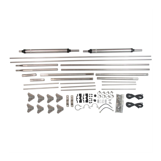
- Page 3 CHAPTER 1 General Description Stainless steel hardware and clamps are sup- Hy-Gain QK-710 will allow plied for-all electrical and most mechanical conversion of the Explorer 14 antenna to connections. A driven element support rope is cover either the 30, 20, 15 and 10 meter bands supplied to help support the additional weight or the 40, 20, 15, and 10 meter bands.
- Page 4 1/8 inch! Double and Triple checkALL dimensions after assembly. Figure 1 Capacity- Hat Clamp Assembly of the QK-710 for 7 MHz Remove the DE-3 (7/16" x 37") and the 1/2" Operation compression clamps (older system) or the #6...
- Page 5 Use the 11/2" aluminum extension straps, #1024 x 1" bolts and #10-24 hex nuts to In addition to the capacity-hat assemblies, extend the sleeve spacer insulators to 7 select the following parts: inches. Assemble the element with the drain holes of the 20 meter trap facing toward the ground.
- Page 6 For antenna heights above 80 feet, use Line 2. Antenna heights less than 35 feet are not recommended. • Figure 3 Assembly of the QK-710 for 10 MHz Operation Remove the DE-3 (7/16" x 37") and the 1/2" Retighten these two clamps securely on both compression clamps (older system) or the #6 sides of the antenna.
- Page 7 Select the following Assemble these parts as shown in Figure 4. Use the 1 1/2" aluminum extension straps, #10-24 x 1" bolts and # 10-24 hex nuts to extend the sleeve spacer insulators to 7 inches. Figure 4 Antenna Dimensions for Operation of the Explorer 14 at 10.1 MHz...
- Page 8 Assemble the element with the drain holes of Descriptio the 20 meter trap facing toward the ground. Also, adjust sections D-3 and D-4 to the dimensions shown in Figure 4. Assemble the beta match extension as shown in Figure 5. Remove the existing beta shorting clamp assembly from the Explorer 14 and reassemble it on the end of the extension, as shown.
- Page 9 CHAPTER 9 Installation Attachment of Driven Element Support IMPORTANT Ropes The Explorer 14, plus 7 or 10 MHz, Due to the element tip loading produced by makes a fairly large antenna and requires the large 20 meter traps, we recommend that some consideration as to how you will you add vertical support ropes to the central safely get it to the top of your tower.
- Page 10 VSWR Curves for 30 and 40 Meters NOTE: The VSWR on 20 meters may be slightly higher than that of the Explorer 14 These VSWR Curves are typical for this alone. This is normal. antenna mounted between 35 and 80 feet above ground, horizontally polarized.
- Page 11 CHAPTER 11 Operation Connect the end of your transmission line to a Telex does not recommend the use of any type good quality SWR meter or Thruline© watt- of conductive paste within the element as- meter and then to your radio. While using semblies.
- Page 12 CHAPTER 12 Usually you can isolate problems that occur in Troubleshooting either your antenna or feedline/feedpoint. If If you encounter problems with the operation you experience high VSWR on all bands, your of your Explorer 14 plus 7 (or 10), follow problem is probably in the feedline or balun.
- Page 13 If you are unable to resolve your problem or if under warranty. (See separate sheet for Telex you need to order replacement parts, you warranty.) should contact the Hy-Gain Customer Service Department in Starkville, MS. All requests, inquiries or warranty claims should be made to:...
- Page 14 Insulator, beta support, bottom ............. 2 465600 Insulator, beta support, top ............2 878306 Parts Pack, QK-710, stainless steel hardware .........1 500152 Bolt, 3/8"-16 x 2", hex head ............2 500154 Bolt, tap; 5/16"-18 x 3 1/2", hex head ..........1 500157 Bolt, # 10-24 x 2", hex head.............
- Page 15 Converting American Measurements to Metric Use this scale to identify lengths of bolts, 1 inch (1") = 2.54 cm diameters of tubes, etc.. The American inch (1") 1 foot (1) = 30.48 cm and foot (1) can be converted to centimeters in this way.
- Page 16 VSWR RECORD At t a c h m e n t 1 PRINTED IN U.S.A. C o p y r i g h t © 1990 by Hy-Gain. All r i g h t s reserved 30 MAR 1990...
Need help?
Do you have a question about the QK-710 and is the answer not in the manual?
Questions and answers