Advertisement
Available languages
Available languages
Quick Links
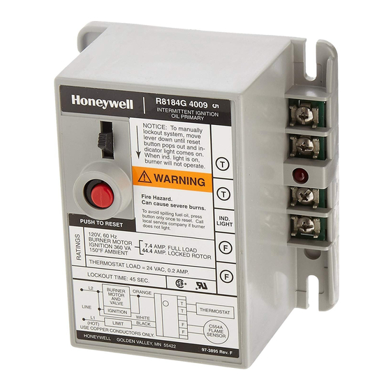
R8184G PROTECTORELAY
OIL PRIMARY
APPLICATION
The intermittent ignition oil primary control operates the
oil burner, oil valve (if desired) and the ignition
transformer in response to a call for heat from the
thermostat. Through a C554 Cad Cell Flame Sensor, the
R8184 monitors the burner flame and shuts down the
system on ignition failure or on flame failure during the
run cycle. A light emitting diode (LED) on the terminal
strip lights when the safety switch opens to provide
safety shutdown indication. A manual reset button is
provided to reset the safety switch after lockout.
For convenience in system maintenance, the safety
switch can be manually opened using a lever on the
front of the control. Clock thermostats that power the
clock through the primary control transformer will lose
time during lockout unless backup batteries are
installed.
R8184G is component recognized by Underwriters
Laboratories Inc. and meets their flammability test
requirements for a final enclosure.
INSTALLATION
When Installing this Product...
1. Read these instructions carefully. Failure to follow
them could damage the product or cause a
hazardous condition.
2. Check the ratings given in the instructions and on
the product to make sure the product is suitable
for your application.
3. Installer must be a trained, experienced service
technician.
4. After installation is complete, check out product
operation as provided in these instructions.
INSTALLATION INSTRUCTIONS
CAUTION
Electrical shock hazard.
Disconnect power before beginning installation
to prevent electrical shock or equipment
damage. Make sure combustion chamber is free
of oil or vapor before starting system.
Choose Location
This unit can be mounted on a 4 x 4 in. junction box,
directly on the burner housing or inside the appliance
cabinet. In a replacement application, mount in the
same location as the old control. Line voltage
connections must be in a wiring enclosure, such as a
junction box or the appliance wiring compartment.
Make sure operating temperatures at the selected
location will be within the range of -40° C to +54° C
(-40° F to +130° F).
Make Wiring Connections and
Mount Control
Wiring must comply with all local codes and ordinances.
Before mounting the control, make line voltage
connections as shown in Fig. 3. Splice leads with
solderless connectors. Do not exceed load ratings
shown on the device label.
If cad cell leads are run with line voltage wires, breakout
knockout at the bottom of the low voltage terminal strip
and thread can cell leads through the hole.
If necessary use control as a template to mark and drill
new mounting holes. Mount using No. 6 screws (obtain
locally).
After mounting, make low voltage connections to the
screw terminals. Strip leads 3/8 in. [10 mm] and insert
under terminal screw. See Fig. 3. Connect cad cell leads
to F-F terminals and thermostat leads to T-T terminals.
See Fig. 1.
69-0617EF-01
Advertisement

Related Manuals for resideo R8184G

Summary of Contents for resideo R8184G
- Page 1 -40° C to +54° C installed. (-40° F to +130° F). R8184G is component recognized by Underwriters Laboratories Inc. and meets their flammability test Make Wiring Connections and requirements for a final enclosure.
- Page 2 3 REMOVE PLUG AND ROUTE VIOLET LEADWIRE THROUGH HOLE IN BASE OF R8184. M718A Fig. 1. Typical hookup for R8184G with indicator light and isolated alarm relay. The R8184G4082 (45 sec.) and R8184G4090 (15 sec.) are Wire the control system as shown in Fig. 2.
-
Page 3: Troubleshooting And Maintenance
R8184G PROTECTORELAY OIL PRIMARY 4. Restore power. Burner should restart. If system does not operate as described, proceed to Troubleshooting. TROUBLESHOOTING AND MAINTENANCE IMPORTANT This control contains no field-serviceable parts. Do not attempt to take it apart. Replace entire control if operation is not as described. - Page 4 Resideo Technologies, Inc. 1985 Douglas Drive North, Golden Valley, MN 55422 1-800-468-1502 www.resideo.com 69-0617EF—01 M.S. 09-20 | Printed in United States © 2020 Resideo Technologies, Inc. All rights reserved. This product is manufactured by Resideo Technologies, Inc. and its affiliates.
-
Page 5: Notice D'installation
-40 ° et 54 °C (-40 ° et 130 °F). installées. Raccordement et Installation Le R8184G est un composant certifié UL qui répond aux exigences de leur test d’inflammabilité pour un boîtier Le câblage doit être conforme aux codes et règlements final. - Page 6 3 RETIRER LE BOUCHON ET ACHEMINER LE FIL VIOLET DANS LE TROU SITUÉ À L'INTÉRIEUR DE LA BASE DU R8184. MF718A Fig. 1. Schéma de raccordement type du R8184G avec voyant. Les relais de protection R8184G4082 (45 s) et s'ouvre, les contacts de l'alarme se ferment pour sonner R8184G4090 (15 s) sont équipés de contacts secs pour...
-
Page 7: Vérification Et Maintenance
RÉGULATEUR PRIMAIRE POUR BRÛLEUR AU MAZOUT R8184G Simuler une défectuosité de l’allumage : 1. Suivre les instructions pour la mise en marche du brûleur. Toutefois, ne pas ouvrir le robinet d’alimentation en mazout. 2. L’interrupteur de sécurité devrait verrouiller le système selon la temporisation indiquée sur... - Page 8 Resideo Technologies, Inc. 1985 Douglas Drive North, Golden Valley, MN 55422 1-800-468-1502 www.resideo.com 69-0617EF—01 M.S. 09-20 | Imprimé aux États-Unis © 2020 Resideo Technologies, Inc. Tous droits réservés. Ce produit est fabriqué par Resideo Technologies, Inc. et ses sociétés affiliées.
Need help?
Do you have a question about the R8184G and is the answer not in the manual?
Questions and answers