
Related Manuals for Lennox 10T50


Summary of Contents for Lennox 10T50
- Page 1 Equipment ® Interface Module Installation and Setup Guide (10T50) 507240-03 1/2018 Supersedes 6/2017...
-
Page 2: Table Of Contents
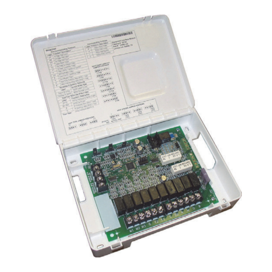
TABLE OF CONTENTS Shipping and Packing List Shipping and Packing List ..............2 Quantity Description Application and Requirements ............2 iComfort® Equipment Interface Module. Indoor Transformer Requirements ........... 2 Installation and setup guide Equipment ..................2 Warranty certificate Installation ...................5 WARNING Configuration Setup ................5 EIM, 24VAC Furnace and iComfort Heat Pump ...... - Page 3 HEAT STAGES HEAT PUMP CAPACITY JUMPER TERMIINALS UNIT TYPE JUMPER JUMPER TERMINALS STATUS LED TERMINALS COMMUNICATION INDICATOR OUTDOOR AIR SENSOR CONNECTIONS ® ICOMFORT CONNECTIONS DISCHARGE AIR SENSOR CONNECTIONS DUAL-FUEL CONNECTIONS 3 AMP FUSE NON-COMMUNICATING TERMINALS Figure 1. Terminals and LEDs...
- Page 4 EIM with Air Hander or Furnace (Indoor Unit) and either a Air Conditioner or Heat Pump (Outdoor Unit) tions, additional components may need to be added, see figure 5 on page 8. ICOMFORT WI-FI ICOMFORT 24VAC Air Handler or iComfort Series Equipment Interface Furnace (Indoor Unit) Thermostat...
-
Page 5: Installation
The iComfort series thermostat without the Equipment Interface Module 2. Set the EIM Heat Stage Jumper to the applicable number of heat pump heating stages. (EIM) will work with Lennox branded communicating HVAC equipment. 3. Wire according to figure 10. 1. Remove the module cover. -
Page 6: Unit Type Jumpers
Unit Type Jumpers 24VAC Heat Pump Size Setting Set the unit type jumper for the type of indoor unit being used (see figure Heat pump size must be configured when using a non-communicating heat 2 and table 4). The factory default setting is IFC. If jumper is missing from pump using the Heat Pump Size jumper (see figure 4 and table 5). -
Page 7: Heat Stage Jumpers
Heat Stage Jumpers Dual-Fuel Terminal Connections Use the following table to set the heat stage jumpers. Table 7. Dual-Fuel Terminals Label Description Function Table 6. Heat Stage Jumpers The pre -coil discharge air sensor should Air Handler Heat Furnace Heat Stages Heat Pump Stages be installed downstream of the gas heat Stages... -
Page 8: Conventional Terminal Connections
Heat pump reversing valve When power off/ or control reset, 24VAC (24 VAC = heat) 3. Touch the Lennox icon on the thermostat home screen and hold until power shall not be present on the O ter- minal. the installer warning screen appears. -
Page 9: Icomfort Wi-Fi Commissioning (Conventional Outdoor Unit)
IMPORTANT If any jumpers were set incorrectly AFTER commissioning was completed, then reposition jumpers to correct positions. Re-running the commissioning procedure will be required at the iComfort series thermostat. iComfort Wi-Fi Commissioning (Conventional Outdoor Unit) Both unit capacity and number of compressor stages are required to be configured through the iComfort series thermostat. -
Page 10: Unit Dimensions
Unit Dimensions DUAL−FUEL WITH DEFROST TEMPERING (EIM, 24VAC Furnace and Communicating Heat Pump) ICOMFORT WI-FI ICOMFORT 6” (152mm) iComfort Series Equipment Interface Thermostat Model (EIM) Furnace NOTE: iComfort Wi-Fi Thermostat with firmware version 2.1 or higher) iComfort ® -enabled Heat Pump (Outdoor Unit) 8”... -
Page 11: Field Wiring
Table 10. Wiring Diagrams DUAL−FUEL WITH DEFROST TEMPERING Indoor Outdoor System Diagram (EIM, Communicating Furnace and 24VAC Heat Pump Unit Unit Hot Water Coil with ICOMFORT Aquastat Blower Conventional iComfort Figure 17 on page 14 WI-FI Control Accessories - De- ICOMFORT humidifiers, humidi- Conventional... - Page 12 ICOMFORT SERIES ICOMFORT SERIES THERMOSTAT THERMOSTAT REMOVE JUMPER BETWEEN R AND W2 IF PRESENT. IT MAY CAUSE ERRONEOUS ALERT CODE 125. Figure 13. Dual-Fuel - iComfort Furnace with Conventional Heat Pump Figure 11. Conventional Air Hander with Conventional Heat Pump ICOMFORT SERIES ICOMFORT SERIES THERMOSTAT...
- Page 13 Figure 15. Dual-Fuel - iComfort Furnace, iHarmony Zoning with Conventional Heat Pump...
- Page 14 ICOMFORT SERIES THERMOSTA T Figure 16. Baseboard Heat - Conventional Air Handler (CBX32MV(-6) or CBX40UHV) with either a iComfort Air Conditioner or Heat Pump REMOVE JUMPER BETWEEN R AND W2 IF PRESENT. IT MAY CAUSE ERRONEOUS ALERT CODE 125. Figure 17. Hot Water Coil Heat with Aquastat Blower Control - Conventional Air Handler (CBX32MV(-6) or CBX40UHV)
- Page 15 ICOMFORT SERIES THERMOSTAT REMOVE JUMPER BETWEEN R AND W2 IF PRESENT. IT MAY CAUSE ERRONEOUS ALERT CODE 125. Figure 18. Optional Accessories with Conventional Outdoor Unit...
- Page 16 ICOMFORT SERIES THERMOSTAT REMOVE JUMPER BETWEEN R AND W2 IF PRESENT. IT MAY CAUSE ERRONEOUS ALERT CODE 125. Figure 19. Optional Accessories with Conventional Indoor Unit...
-
Page 17: Alert Codes And Troubleshooting
Alert Codes and Troubleshooting Error codes are transmitted to the thermostat. No codes are stored in the EIM. Table 11. Alert Codes and Troubleshooting Alert Code Priority Applicable System Alert Text Component or System Operational State How to clear the alert code and Troubleshooting Tip Condition Component(s) - Page 18 Table 11. Alert Codes and Troubleshooting Alert Code Priority Applicable System Alert Text Component or System Operational State How to clear the alert code and Troubleshooting Tip Condition Component(s) √ This alert code may indicate transformer overload ing. √ Check the voltage and line power frequency. √...
- Page 19 Table 11. Alert Codes and Troubleshooting Alert Code Priority Applicable System Alert Text Component or System Operational State How to clear the alert code and Troubleshooting Tip Condition Component(s) √ Configuration jumper missing on equipment inter face module. Automatically clears after Air handler jumper is the missing or incor rectly √...
- Page 20 Table 11. Alert Codes and Troubleshooting Alert Code Priority Applicable System Alert Text Component or System Operational State How to clear the alert code and Troubleshooting Tip Condition Component(s) √ Interlock relay is energized, but input is not sensed after three seconds.