Table of Contents
Advertisement
Quick Links
Advertisement
Table of Contents

Subscribe to Our Youtube Channel
Related Manuals for Silex technology BR-400AN


Summary of Contents for Silex technology BR-400AN
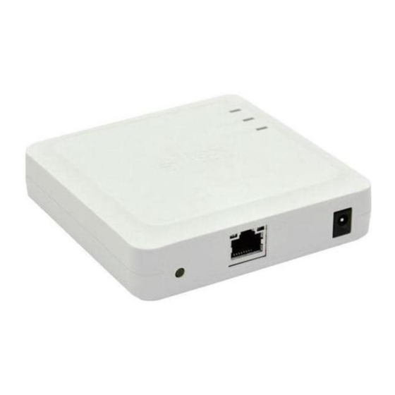
- Page 1 Mesh Network System BR-400AN Installation Manual WA105350XB...
-
Page 2: Table Of Contents
Appendix ..........................14 Bulk IP Address Configuration (When DHCP is Not Installed) ..........14 List of Configuration Items ...................... 17 Wireless Channel Selection ....................19 How to Fix BR-400AN ......................20 Layout Sample ........................22 Basic Use of Mesh Monitor ..................... 24... -
Page 3: Introduction
NTRODUCTION This document describes the initial configuration and installation methods for BR-400AN. BR-400AN can configure the Mesh type wireless network (hereinafter, “Mesh network”). Wired and wireless network devices can join the Mesh network and they can communicate with each other. -
Page 4: Layout
AYOUT 2.1 Preparing Floor Plan Image Please prepare the floor plan image of the floor where BR-400AN units are to be installed, which meets the following conditions. (1) The scale is clearly indicated, or approximate distance / area can be confirmed. -
Page 5: Determination Of Unit Locations
Mesh network group. * If there is a wall between the BR-400AN units, the radio signals may be blocked. In such a case, install another BR-400AN unit to use as a relay terminal to give an alternative path for the radio signals. -
Page 6: Necessary Items
2.3 Necessary Items Prepare the necessary quantity of BR-400AN units by reading the instructions on the previous chapter. It is recommended to have some extra units in case of emergency or unexpected trouble. <Package contents > ・AC adapter (length of DC cable is 1.75m) ・Wall-mounting Bracket (Type VI), Wall-mounting screw (4), Board anchor(4) -
Page 7: Configuration
3.1 Determination of Configuration Points: (1) Network Loop Avoidance should be set to ENABLE on the BR-400AN unit which connects to the backbone network. For other units, set it to DISABLE. (2) When several Mesh groups are configured, use a different Mesh group and channel for each. -
Page 8: Configuration File
Use AMC Manager® to create the configuration file to write. *When the login password is not set to BR-400AN, please include that setting to the configuration file. If the login password is not set, the bulk configuration does not perform correctly. - Page 9 Pre-Shared Key PIeq3141593 * For other settings of BR-400AN, refer to Appendix 5.2. 3. When the Save Configuration File dialog is displayed, specify the file name and click Save. This time, the file name is set to “SampleMesh01-STD” as example.
- Page 10 Based on the configuration file saved at 3, create the configuration file for the BR-400AN unit that connects to the backbone network. From the menu, click Setting - Create Configuration File - Edit Existing File and open the configuration file “SampleMesh01-STD.cfg” that you have created.
-
Page 11: Configuration Write
3.3 Configuration Write The following explains the method of bulk configuration using the configuration file. 1. Put all BR-400AN units on one place and connect a PC to one of them using a network cable. Turn on all units. * When there are many BR-400AN units to configure, prepare the power strip. Or divide them into small groups (8 units or so) and then configure by each group. - Page 12 4. Check the check boxes of BR-400AN units to configure in bulk and click Start. When the password entry dialog is displayed, enter the default password (root). �� For configuration under the environment where DHCP is not installed, refer to Appendix 5.1 Bulk IP Address Configuration.
-
Page 13: Installation
(5) 4.1.1 Installation to Backbone Network Connect BR-400AN to the backbone network using a network cable and turn on it. If the sample configuration of previous chapter is used, install the unit of “SampleMesh01-BC”. * When two or more BR-400AN units are connected to the backbone network, install one of them... -
Page 14: Installation Of Others
* If the WLAN LED blinks, it means that the BR-400AN unit has failed to join the existing Mesh network. Adjust the location or direction of installation or otherwise install another unit to use it as a relay device to expand the wireless distance. -
Page 15: Operation Check
4.2 Operation Check Use Mesh Monitor to see if the information can be retrieved from the installed BR-400AN units. Route status check using Mesh Monitor The Mesh route of the installed units can be checked using Mesh Monitor. Check that the installed units are turned on and the Mesh route is established for each unit. -
Page 16: Appendix
5.1 Bulk IP Address Configuration (When DHCP is Not Installed) When BR-400AN does not have a fixed IP address and is turned on in the environment where DHCP is not installed, BR-400AN starts with a LinkLocal Address. It is possible to use BR-400AN with the LinkLocal Address, but usually, the fixed IP address is used in many cases. - Page 17 When the BR-400AN units are displayed in the list, select the units to change the IP address and click Settings - Bulk Configuration. (3) Bulk Configuration In the Bulk Configuration window, click IP Configuration. When the IP address configuration dialog is displayed, enter the setting.
- Page 18 (4) Restart To take effect of the new IP address, restart BR-400AN using AMC Manager®. Select the BR-400AN units from the list and click Settings - Restart from the menu. The device restart window is displayed. Check that the device status is ‘Waiting’ and click Restart. When the result of restart is displayed, click Close.
-
Page 19: List Of Configuration Items
Category Name System Password root Set the password for BR-400AN. Configuration This is used when BR-400AN is configured via Web browser or by using AMC Manager®. Host Name SX-MESH-001 This host name is displayed on AMC Manager® and Mesh Monitor. - Page 20 Wireless LAN I/F 2 Shard Secret RADIUSKEY01 Others Time before turning into Set the period of time until the Configuration Mode configuration mode turns on after the push switch is pressed. * For details on each configuration item, refer to “BR-400AN User’s Manual”.
-
Page 21: Wireless Channel Selection
* BR-400AN has the following restrictions on use of the DFS band. - If radar signals are detected again during the radar monitoring period (1min) that comes after radar signals are detected when BR-400AN is started or operating, BR-400AN may not be able to join the network of adjacent MP/MAP. -
Page 22: How To Fix Br-400An
① Make sure that top surface of BR-400AN (surface with Silex logo) faces upward. ② Prepare a nonmetallic table (wood table is good). ③ Set BR-400AN to a higher position as possible. Do not place it on the floor. Do not place BR-400AN under the following conditions. It causes malfunction. - Page 23 Radio characteristics BR-400AN emits the radio signal as below. Make sure that the top surface of BR-400AN faces the destination device.
-
Page 24: Layout Sample
5.5 Layout Sample Sample1. SILEX TECHNOLOGY Corporate Headquarters Mesh Group Name: silex01 Channel: 6ch Traffic Loop Avoidance: The unit A, B that connect to the existing LAN…ON Other than A,B…OFF silex01 Only one Mesh network is established because wireless communication can be reached across the floors through the stairwell. - Page 25 Sample 3. △△ center Mesh Group Name A:Room A, Channel a:36ch Mesh Group Name b:Room B, Channel b:40ch Room A Room B Traffic Loop Avoidance : OFF for all * If the radio signals are hard to reach even on the same floor, a different Mesh group name needs to be set for each.
-
Page 26: Basic Use Of Mesh Monitor
5.6 Basic Use of Mesh Monitor The following explains how to check the Mesh network using Mesh Monitor. Start AMC Manager® and click the icon Start the plug-in tools in the tool bar and choose Start Mesh Monitor. Mesh Monitor will start. Click the icon Add floor to display the Add Floor Information window. - Page 27 Drag and drop a Mesh device on the floor map from the device list. Repeat 4 to allocate Mesh devices on the floor map. Every time when a Mesh device is allocated on the floor map, Mesh Monitor adds Mesh routes based on the information of that device. * Up to 32 Mesh devices can be allocated per floor.
- Page 28 Contact Information +1-657-218-5199 support@silexamerica.com Europe +49-2154-88967-0 support@silexeurope.com Japan +81-774-98-3981 support@silex.jp...
Need help?
Do you have a question about the BR-400AN and is the answer not in the manual?
Questions and answers