Table of Contents
Advertisement
Quick Links
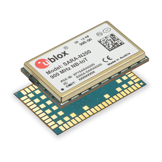
SARA-N2 / N3 series
Multi-band NB-IoT (LTE Cat NB1 / NB2) modules
System integration manual
Abstract
This document describes the features and the system integration of the SARA-N2 series and the
SARA-N3 series NB-IoT modules. These modules are a complete and cost efficient solution offering
from single-band up to multi-band data transmission for the Internet of Things technology in the
compact SARA form factor.
UBX-17005143 - R13
C1-Public
SARA-N2 / N3
www.u-blox.com
Advertisement
Table of Contents

Subscribe to Our Youtube Channel
Related Manuals for Ublox SARA-N2 Series


Summary of Contents for Ublox SARA-N2 Series
- Page 1 SARA-N2 / N3 Abstract This document describes the features and the system integration of the SARA-N2 series and the SARA-N3 series NB-IoT modules. These modules are a complete and cost efficient solution offering from single-band up to multi-band data transmission for the Internet of Things technology in the compact SARA form factor.
-
Page 2: Document Information
SARA-N2 / N3 series - System integration manual Document information Title SARA-N2 / N3 series Subtitle Multi-band NB-IoT (LTE Cat NB1 / NB2) modules Document type System integration manual Document number UBX-17005143 Revision and date 14-Oct-2020 Disclosure restriction C1-Public Product status Corresponding content status Functional sample Draft... -
Page 3: Table Of Contents
SARA-N2 / N3 series - System integration manual Contents Document information ..........................2 Contents ................................3 System description ..........................6 Overview ................................ 6 1.2 Architecture ..............................8 1.3 Pin-out ................................9 1.4 Operating modes ............................13 1.5 Supply interfaces ............................15 1.5.1 Module supply input (VCC) ...................... - Page 4 SARA-N2 / N3 series - System integration manual 2.4.1 Cellular antenna RF interface (ANT) ..................... 45 2.4.2 Bluetooth antenna RF interface (ANT_BT) ................. 52 2.4.3 Antenna detection interface (ANT_DET)..................52 2.5 SIM interface .............................. 55 2.6 Serial interfaces ............................60 2.6.1 Main primary UART interface ......................
- Page 5 SARA-N2 / N3 series - System integration manual 4.3 ATEX / IECEx conformance ........................85 4.4 Chinese conformance ..........................86 4.5 Taiwanese conformance ......................... 87 4.6 Australian conformance .......................... 87 Product testing ........................... 88 5.1 u-blox in-series production test ......................88 5.2 Test parameters for OEM manufacturer .....................
-
Page 6: System Description
–40 to +85 °C, with extremely low power consumption. SARA-N2 series include four variants supporting single-band LTE Cat NB1 data communication for Europe, China, APAC and South America, plus a dual-band variant mainly designed for Europe. - Page 7 SARA-N2 / N3 series - System integration manual Table 2 summarizes cellular radio access technology characteristics of SARA-N2 / N3 series modules. Item SARA-N2 series SARA-N3 series Protocol stack 3GPP release 13 3GPP release 14 Radio Access Technology LTE Category NB1...
-
Page 8: Architecture
Antenna detection V_INT Figure 1: SARA-N2 series modules block diagram ☞ The “02" product version of SARA-N2 series modules do not support the following interfaces, which should not be driven by external devices: Antenna detection DDC (I2C) interface 32.768 kHz... -
Page 9: Pin-Out
RX/TX path • RX low-loss filters • 38.4 MHz (SARA-N2 series) / 26.0 MHz (SARA-N3 series) crystal oscillator for the clock reference in active-mode and connected-mode The Baseband and Power Management section is composed of the following main elements: •... - Page 10 Data output Circuit 104 (RXD) in ITU-T V.24 UART (main) SARA-N2 series modules: • Supporting AT communication, FOAT and FW upgrade via dedicated tool • VCC voltage level SARA-N3 series modules: • Supporting AT communication and FOAT •...
- Page 11 Pin No Description Remarks Data input Circuit 103 (TXD) in ITU-T V.24 SARA-N2 series modules: • Supporting AT communication, FOAT and FW upgrade via dedicated tool • VCC voltage level, without internal pull-up/down SARA-N3 series modules: • Supporting AT communication and FOAT •...
- Page 12 SARA-N2 / N3 series - System integration manual Function Pin name Modules Pin No Description Remarks UART RXD_FT SARA-N3 28 Data output Circuit 104 (RXD) in ITU-T V.24, at V_INT voltage level. (additional) Supporting FW update via u-blox EasyFlash tool and Trace log.
-
Page 13: Operating Modes
SARA-N2 / N3 series modules are fully ready to operate when in active mode. Then, the SARA-N2 series modules switch from active mode to deep sleep mode whenever possible, entering the lowest possible power mode, with current consumption in the ~µA range. The UART... - Page 14 Active Sleep No RF Tx/Rx in progress • Network paging • Data received over UART • Expiration of Periodic Update Timer Figure 3: SARA-N2 series modules’ operating modes transitions powered Apply VCC Remove VCC Power off Switch OFF: Switch ON: •...
-
Page 15: Supply Interfaces
SARA-N2 / N3 series - System integration manual Supply interfaces 1.5.1 Module supply input (VCC) The modules must be supplied via all the three VCC pins that represent the module power supply input. The VCC pins are internally connected to the RF power amplifier and to the integrated Power Management Unit: all supply voltages needed by the module are generated from the VCC supply by integrated voltage regulators, including V_INT (digital interfaces supply) and VSIM (SIM card supply). -
Page 16: Rtc Supply (V_Bckp)
The current consumption peaks occur when the module is in the connected (transmitting) mode and the value of these peaks is strictly dependent on the transmitted power, which is regulated by the network. See the electrical specification section in the SARA-N2 series data sheet... -
Page 17: Interfaces Supply Output (V_Int)
The V_INT voltage regulator output of SARA-N2 series modules is disabled (i.e. 0 V) when the module is switched off, and it can be used to monitor the operating mode when the module is switched on: •... -
Page 18: System Function Interfaces
Module power-on 1.6.1.1 Switch-on events When the SARA-N2 series modules are in the non-powered mode (i.e. switched off, with the VCC module supply not applied), the switch on routine of the module can be triggered by: • Rising edge on the VCC supply input to a valid voltage value for module supply, starting from a voltage value lower than 1.8 V, so that the module switches on applying a proper VCC supply within... - Page 19 LOW when radio is OFF Greeting text System state ~3.5 s Figure 8: SARA-N2 series power-on sequence from not-powered mode Figure 9 shows the switch on sequence of SARA-N3 modules starting from the non-powered mode: • The external supply is being applied to the VCC inputs.
-
Page 20: Module Power-Off
1.6.2 Module power-off The SARA-N2 series modules enter the non-powered mode by removing the VCC supply. The switch-off routine of the SARA-N3 series modules can be properly triggered, with storage of current parameter settings in the module’s non-volatile memory and clean network detach, by: •... -
Page 21: Module Reset
Voltage selection of interfaces (VSEL) ☞ The digital interfaces’ voltage selection functionality is not available in SARA-N2 series modules. The digital I/O interfaces of the SARA-N3 series modules (the UARTs, I2C, and GPIOs pins) operate at the V_INT voltage, which can be set to 1.8 V or 2.8 V using the VSEL input: •... -
Page 22: Antenna Interface
The nominal characteristic impedance of the antenna RF connection must match the ANT pin 50 impedance. Frequency range See the SARA-N2 series data sheet The required frequency range of the antenna SARA-N3 series data sheet depends on the operating bands supported by the cellular module. -
Page 23: Bluetooth Antenna Rf Interface (Ant_Bt)
SIM_RST pins, which is available to connect an external SIM / UICC. The SIM interface of the SARA-N2 series modules can operate at 1.8 V (VSIM domain), with activation and deactivation of the SIM interface implemented according to the ISO-IEC 7816-3 specifications. -
Page 24: Serial Interfaces
SARA-N2 / N3 series modules provide the following serial communication interfaces: • Main primary UART interface (see 1.9.1): In the VCC voltage domain (~3.6 V) on the SARA-N2 series modules, supporting: AT communication ▪ FW upgrades by means of the FOAT feature ▪... - Page 25 SARA-N2 / N3 series - System integration manual SARA-N3 series modules include the RXD, TXD, CTS, RTS, DTR, DSR, DCD, RI pins as main primary UART interface, supporting: • AT communication • FW upgrades by means of the FOAT feature The main characteristics of the SARA-N3 series modules main primary UART interface are the following: •...
- Page 26 1.9.1.3 UART and deep sleep mode To limit the current consumption, SARA-N2 series modules automatically enter deep-sleep mode whenever possible, that is if there is no data to transmit or receive. When in deep-sleep mode the UART interface is still completely functional and the SARA-N2 module can accept and respond to any AT command.
-
Page 27: Secondary Auxiliary Uart Interface
Data lines (RXD_AUX as module data output, TXD_AUX as module data input) are provided 1.9.3 Additional UART interface SARA-N2 series modules include the GPIO1 pin as additional UART interface, supporting: • Diagnostic trace log The characteristics of the SARA-N2 modules’ additional UART interface are: •... -
Page 28: Ddc (I2C) Interface
1.10 ADC ☞ ADC interface is not available in the SARA-N2 series modules. The SARA-N3 series modules include two Analog-to-Digital Converter input pins, ANT_DET and ADC1, configurable via dedicated AT command (for further details, see the SARA-N2 / SARA-N3 series AT commands manual [4]). -
Page 29: Reserved Pins (Rsvd)
SARA-N2 / N3 series - System integration manual SARA-N3 series modules include General Purpose Input/Output pins that can be configured via u-blox AT commands (for further details, see the AT commands manual [4], +UGPIOC, +URING AT commands). The internal power domain for the GPIO pins is V_INT, with 1.8 V or 2.8 V voltage value set according to external VSEL pin configuration. -
Page 30: Design-In
SARA-N2 / N3 series - System integration manual Design-in Overview For an optimal integration of SARA-N2 / N3 series modules in the final application board, follow the design guidelines stated in this section. Every application circuit must be properly designed to guarantee the correct functionality of the related interface, however a number of points require higher attention during the design of the application device. -
Page 31: Supply Interfaces
SARA-N2 / N3 series - System integration manual 2.2 Supply interfaces 2.2.1 Module supply input (VCC) 2.2.1.1 General guidelines for VCC supply circuit selection and design All the available VCC pins must be connected to the external supply minimizing the power loss due to series resistance. - Page 32 SARA-N2 / N3 series - System integration manual nominal voltage (e.g. ~12 V), whereas a linear charger is the typical choice when the charging source has a relatively low nominal voltage (~5 V). If both a permanent primary supply / charging source (e.g. ~12 V) and a rechargeable back-up battery (e.g.
- Page 33 Maximum pulse and DC discharge current: the non-rechargeable battery with its output circuit must be capable of delivering to VCC pins the specified average current during a transmission at maximum power (see the SARA-N2 series data sheet and SARA-N3 series data sheet more details).
- Page 34 SARA-N2 / N3 series - System integration manual Figure 14 shows an example of connection of the SARA-N2 / N3 series module with a primary battery. Table 9 lists different battery pack part numbers that can be used. Battery pack SARA-N2/N3 Figure 14: Suggested schematic design for the VCC voltage supply application circuit using a LiSOCl primary battery...
- Page 35 VCC pins within the specified operating range and must be capable of delivering to VCC pins the specified average current during a transmission at maximum power (see SARA-N2 series data sheet and SARA-N3 series data sheet [2]).
- Page 36 SARA-N2 / N3 series - System integration manual Figure 16 and the components listed in Table 11 show an example of a power supply circuit, where the module VCC is supplied by a step-down switching regulator capable of delivering the specified maximum current to the VCC pins, with low output ripple and with fixed switching frequency in PWM.
- Page 37 Power capabilities: the LDO linear regulator with its output circuit must be capable of providing a proper voltage value to the VCC pins and of delivering to VCC pins the specified maximum average current during a transmission at maximum power (see the SARA-N2 series data sheet SARA-N3 series data sheet [2]) •...
- Page 38 SARA-N2 / N3 series - System integration manual 2.2.1.6 Additional guidelines for VCC supply circuit design To reduce voltage drops, use a low impedance power source. The resistance of the power supply lines (connected to the VCC and GND pins of the module) on the application board and battery pack should also be considered and minimized: cabling and routing must be as short as possible to minimize power losses.
- Page 39 SARA-N2 / N3 series - System integration manual 2.2.1.7 Guidelines for VCC supply layout design Good connection of the module VCC pins with DC supply source is required for correct RF performance. Guidelines are summarized in the following list: • All the available VCC pins must be connected to the DC source.
-
Page 40: Rtc Supply (V_Bckp)
Guidelines for V_BCKP circuit design ☞ The RTC supply (V_BCKP pin) is not available on SARA-N2 series modules. V_BCKP is the Real Time Clock (RTC) supply of SARA-N3 series modules. When VCC voltage is within the valid operating range, the internal Power Management Unit (PMU) supplies the RTC and the same supply voltage is available on the V_BCKP pin. -
Page 41: Interfaces Supply Output (V_Int)
SARA-N2 / N3 series - System integration manual 2.2.3 Interfaces supply output (V_INT) 2.2.3.1 Guidelines for V_INT circuit design The V_INT digital interfaces supply output can be mainly used to: • Indicate when the SARA-N2 modules’ radio is on (see section 1.6.1 for more details) •... -
Page 42: System Functions Interfaces
Guidelines for PWR_ON circuit design ☞ The PWR_ON input pin is not available in SARA-N2 series modules. As described in SARA-N3 series data sheet [2], the module has an internal pull-up resistor on the PWR_ON input line, so an external pull-up is not required on the application board. -
Page 43: Module Reset (Reset_N)
2.3.2.1 Guidelines for RESET_N circuit design As described in SARA-N2 series data sheet and SARA-N3 series data sheet [2], the modules have an internal pull-up resistor on the RESET_N input line, so an external pull-up is not required on the application board. -
Page 44: Voltage Selection Of Interfaces (Vsel)
Guidelines for VSEL circuit design ☞ The VSEL input pin is not available in SARA-N2 series modules. The state of the VSEL input pin is used to configure the V_INT supply output and the voltage domain for the generic digital interfaces of the SARA-N3 series modules (the UARTs, I2C, and GPIOs pins): •... -
Page 45: Antenna Interface
SARA-N2 / N3 series - System integration manual 2.4 Antenna interface The ANT pin, provided by all the SARA-N2 / N3 series modules, represents the RF input/output used to transmit and receive the RF cellular signals: the antenna must be connected to this pin. The ANT pin has a nominal characteristic impedance of 50 ... - Page 46 SARA-N2 / N3 series - System integration manual In both cases, selecting an external or an internal antenna, observe these recommendations: • Select an antenna providing optimal return loss (or V.S.W.R.) figure over all the operating frequencies. • Select an antenna providing optimal efficiency figure over all the operating frequencies. •...
- Page 47 SARA-N2 / N3 series - System integration manual Guidelines for RF transmission line design The transmission line from the ANT pad up to antenna connector or up to the internal antenna pad must be designed so that the characteristic impedance is as close as possible to 50 . The transmission line can be designed as a micro strip (consists of a conducting strip separated from a ground plane by a dielectric material) or a strip line (consists of a flat strip of metal which is sandwiched between two parallel ground planes within a dielectric material).
- Page 48 SARA-N2 / N3 series - System integration manual If the distance between the transmission line and the adjacent GND area (on the same layer) does not exceed 5 times the track width of the micro strip, use the “Coplanar Waveguide” model for the 50 calculation.
- Page 49 SARA-N2 / N3 series - System integration manual Guidelines for RF termination design The RF termination must provide a characteristic impedance of 50 as well as the RF transmission line up to the RF termination itself, to match the characteristic impedance of the ANT pin of the module.
- Page 50 SARA-N2 / N3 series - System integration manual Examples of antennas Table 16 lists some examples of possible internal on-board surface-mount antennas Manufacturer Part number Product name Description Taoglas PA.710.A Warrior Cellular SMD Antenna 698..960 MHz, 1710..2170 MHz, 2300..2400 MHz, 2490..2690 MHz 40.0 x 6.0 x 5.0 mm Taoglas PCS.06.A...
- Page 51 SARA-N2 / N3 series - System integration manual Table 17 lists some examples of possible internal off-board antennas with cable and connector. Manufacturer Part number Product name Description Taoglas FXUB63.07.0150C Cellular PCB Antenna with cable and U.FL connector 698..960 MHz, 1575.42 MHz, 1710..2170 MHz, 2400..2690 MHz 96.0 x 21.0 mm Taoglas FXUB66.07.0150C...
-
Page 52: Bluetooth Antenna Rf Interface (Ant_Bt)
The ANT_BT pin can be left unconnected or it can also be connected to GND. 2.4.3 Antenna detection interface (ANT_DET) ☞ The antenna detection interface is not supported by "02" product version of SARA-N2 series modules. 2.4.3.1 Guidelines for ANT_DET circuit design... - Page 53 SARA-N2 / N3 series - System integration manual The antenna detection circuit and diagnostic circuit shown in Figure 28 Table 19 are explained below: • When antenna detection is forced by the dedicated AT command (see SARA-N2 / N3 series AT commands manual [4]), the ANT_DET pin generates a DC current measuring the resistance (R2) from the antenna connector (J1) provided on the application board to GND.
- Page 54 SARA-N2 / N3 series - System integration manual 2.4.3.2 Guidelines for ANT_DET layout design Figure 29 describes the recommended layout for the antenna detection circuit to be provided on the application board to achieve antenna detection functionality, implementing the recommended schematic described in the previous Figure 28 Table...
-
Page 55: Sim Interface
SARA-N2 / N3 series - System integration manual 2.5 SIM interface 2.5.1.1 Guidelines for SIM circuit design Guidelines for SIM cards, SIM connectors and SIM chips selection The ISO/IEC 7816, the ETSI TS 102 221 and the ETSI TS 102 671 specifications define the physical, electrical and functional characteristics of Universal Integrated Circuit Cards (UICC) which contains the Subscriber Identification Module (SIM) integrated circuit that securely stores all the information needed to identify and authenticate subscribers over the cellular network. - Page 56 SARA-N2 / N3 series - System integration manual Guidelines for SIM card connection An application circuit for the connection to a removable SIM card placed in a SIM card holder is described in Figure Follow these guidelines connecting the module to a SIM connector: •...
- Page 57 Guidelines for single SIM card connection with detection ☞ The SIM card detection functionality over GPIO is not supported by the SARA-N2 series and by the “00” product version of the SARA-N3 series modules. An application circuit for connecting to a single removable SIM card placed in a SIM card holder is...
- Page 58 SARA-N2 / N3 series - System integration manual • Connect one pin of the normally-open mechanical switch integrated in the SIM connector (as the SW2 pin in Figure 32) to the GPIO5 input pin, providing a weak pull-down resistor (e.g. 470 k, as R2 in Figure 32).
- Page 59 SARA-N2 / N3 series - System integration manual 2.5.1.2 Guidelines for SIM layout design The layout of the SIM card interface lines (VSIM, SIM_CLK, SIM_IO, SIM_RST) may be critical if the SIM card is placed far away from the SARA-N2 / N3 series modules or in close proximity to the RF antenna: these two cases should be avoided or at least mitigated as described below.
-
Page 60: Serial Interfaces
SARA-N2 / N3 series - System integration manual 2.6 Serial interfaces 2.6.1 Main primary UART interface ☞ The SARA-N2 modules do not support hardware flow control functionality over the CTS and RTS pins. The SARA-N2 modules do not include the DTR, DSR, DCD and RI pins. ☞... - Page 61 SARA-N2 / N3 series - System integration manual DTE 3.0 V supply can be also ramped up before the module V_INT 1.8 V supply), using the V_INT supply output of the module as the 1.8 V supply for the voltage translators on the module side, and the 3.0 V supply rail application processor on the application processor side.
- Page 62 SARA-N2 / N3 series - System integration manual Guidelines for SARA-N3 series modules’ TXD and RXD lines connection If RS-232 compatible signal levels are needed, two different external voltage translators (e.g. Maxim MAX3237E and Texas Instruments SN74AVC4T774) can be used. The Texas Instruments’ chips provide the translation from 1.8 V / 2.8 V to 3.3 V, while the Maxim chip provides the translation from 3.3 V to RS-232 compatible signal level.
- Page 63 Unidirectional voltage translator SN74LVC1T45 - Texas Instruments Table 23: Parts for SARA-N2 series’ UART interface application circuit with TXD and RXD lines connection to 1.8 V DTE ☞ It is not recommended to use V_INT pin of the SARA-N2 module as control and/or supply line for the external voltage translator.
- Page 64 0Ω 0Ω Figure 41: SARA-N2 series’ UART interface application circuit with TXD, RXD and RING lines connection to 3.3 V DTE Additional considerations If a 1.8 V Application Processor (DTE) is used, the voltage scaling from any UART output of the module (DCE), working at VCC voltage level (3.6 V nominal), to the apposite 1.8 V input of the DTE can be...
-
Page 65: Secondary Auxiliary Uart Interface
SARA-N2 / N3 series - System integration manual 2.6.2 Secondary auxiliary UART interface ☞ SARA-N2 modules do not include a secondary auxiliary UART interface. ☞ SARA-N3 "00" product version do not support a secondary auxiliary UART interface. 2.6.2.1 Guidelines for secondary auxiliary UART circuit design If RS-232 compatible signal levels are needed, two different external voltage translators (e.g. -
Page 66: Additional Uart Interface
2.6.4 DDC (I2C) interface ☞ The DDC (I2C) interface is not supported by the "02" product version of the SARA-N2 series modules: the SDA and SCL lines can be left unconnected. ☞ The DDC (I2C) interface is not supported by the "00" product version of the SARA-N3 series modules: the SDA and SCL lines can be left unconnected. -
Page 67: Adc
SARA-N2 / N3 series - System integration manual 2.7 ADC ☞ ADC interface is not available on the SARA-N2 modules. 2.7.1.1 Guidelines for ADC circuit design The SARA-N3 series modules include two Analog-to-Digital Converter input pins, ANT_DET and ADC1, configurable via a dedicated AT command (for further details, see the SARA-N2 / SARA-N3 series AT commands manual [4]). -
Page 68: General Purpose Input/Output (Gpio)
GPIO4 pin of SARA-N3 series modules providing module status indication • GPIO5 pin of SARA-N3 series modules providing SIM card detection functionality (see section 2.5) • CTS pin set as Network Indicator (see below) or Ring Indicator (see section 2.6.1) SARA-N2 series TestPoint UART for diagnostic GPIO1 Network indicator... -
Page 69: Module Placement
SARA-N2 / N3 series - System integration manual 2.10 Module placement Optimize placement for minimum length of RF line and closer path from DC source for VCC. Make sure that the module, RF and analog parts / circuits are clearly separated from any possible source of radiated energy, including digital circuits that can radiate some digital frequency harmonics, which can produce Electro-Magnetic Interference affecting module, RF and analog parts / circuits’... -
Page 70: Module Footprint And Paste Mask
SARA-N2 / N3 series - System integration manual 2.11 Module footprint and paste mask Figure 48 Table 25 describe the suggested footprint (i.e. copper mask) and paste mask layout for SARA modules: the proposed land pattern layout reflects the modules’ pins layout, while the proposed stencil apertures layout is slightly different (see the F’’, H’’, I’’, J’’, O’’... -
Page 71: Integration In Devices Intended For Use In Potentially Explosive Environments
2.12.1 General guidelines SARA-N211 and SARA-N310 modules are certified as components intended for use in potentially explosive atmospheres (see section and see the “Approvals” section of the SARA-N2 series data sheet for further details), with the following marking: •... -
Page 72: Guidelines For Vcc Supply Circuit Design
The module does not contain blocks which increase the voltage (e.g. like step-up, duplicators, boosters, etc.) The nameplate of the modules is described in the “Product labeling” section of the SARA-N2 series data sheet and the SARA-N3 series data sheet [2]. For additional info and modules’ certificate of compliancy for use in potentially explosive atmospheres, see our website (www.u-blox.com) or contact... - Page 73 SARA-N2 / N3 series - System integration manual Primary and secondary cells and batteries Cells and batteries incorporated into equipment with intrinsic safety “i” protection to potentially explosive gas atmosphere shall conform to the requirements of the IEC 60079-0 [10], IEC 60079-11 [11] ATEX standards.
-
Page 74: Guidelines For Antenna Rf Interface Design
SARA-N2 / N3 series - System integration manual 2.12.3 Guidelines for antenna RF interface design The RF radiating power profile of the SARA-N211 and SARA-N310 modules is compliant to all the applicable 3GPP / ETSI standards, with a maximum of 250 mW RF average power according to the LTE Cat NB1 / NB2 Power Class stated in Table The RF threshold power of the application device integrating a SARA-N211 or SARA-N310 module is... -
Page 75: Schematic For Sara-N2 / N3 Series Module Integration
2.13 Schematic for SARA-N2 / N3 series module integration Figure 49 is an example of a schematic diagram where a SARA-N2 module “02” product version is integrated into an application board, using all the available interfaces and functions of the module. SARA-N2 series External 15pF Connector... - Page 76 SARA-N2 / N3 series - System integration manual Figure 50 shows an example of a schematic diagram where a SARA-N3 “00” product version is integrated into an application board using most of the available interfaces and functions. SARA-N3 series External 15pF Connector 33pF...
-
Page 77: Design-In Checklists
SARA-N2 / N3 series - System integration manual 2.14 Design-in checklists The following are the most important points for simple checks. 2.14.1 Schematic checklist The external DC supply circuit must provide a nominal voltage at VCC pins within the normal operating range limits. -
Page 78: Handling And Soldering
Packaging, shipping, storage and moisture preconditioning For information pertaining to reels and tapes, Moisture Sensitivity levels (MSD), shipment and storage information, as well as drying for preconditioning see the SARA-N2 series data sheet [1], the SARA-N3 series data sheet and the u-blox package information user guide [3]. -
Page 79: Soldering
SARA-N2 / N3 series - System integration manual 3.3 Soldering 3.3.1 Soldering paste Use of "No Clean" soldering paste is strongly recommended, as it does not require cleaning after the soldering process has taken place. The paste listed in the example below meets these criteria. Soldering Paste: OM338 SAC405 / Nr.143714 (Cookson Electronics) Alloy specification:... -
Page 80: Optical Inspection
SARA-N2 / N3 series - System integration manual Cooling phase A controlled cooling avoids negative metallurgical effects (solder becomes more brittle) of the solder and possible mechanical tensions in the products. Controlled cooling helps to achieve bright solder fillets with a good shape and low contact angle. •... -
Page 81: Repeated Reflow Soldering
SARA-N2 / N3 series - System integration manual 3.3.5 Repeated reflow soldering Repeated reflow soldering processes and soldering the module upside down are not recommended. Boards with components on both sides may require two reflow cycles. In this case, the module should always be placed on the side of the board that is submitted into the last reflow cycle. -
Page 82: Casting
SARA-N2 / N3 series - System integration manual 3.3.10 Casting If casting is required, use viscose or another type of silicon pottant. The OEM is strongly advised to qualify such processes in combination with the SARA-N2 / N3 series modules before implementing this in the production. -
Page 83: Approvals
SARA-N2 / N3 series - System integration manual Approvals Approvals overview Product certification approval is the process of certifying that a product has passed all tests and criteria required by specifications, typically called “certification schemes”, which can be divided into three distinct categories: •... -
Page 84: European Conformance
SARA-N2 / N3 series - System integration manual The required certification scheme approvals and relative testing specifications differ depending on the country or the region where the device that integrates SARA-N2 / N3 series modules is intended to be deployed, on the relative vertical market of the device, on type, features and functionalities of the whole application device, and on the network operators where the device is intended to operate. -
Page 85: Atex / Iecex Conformance
250 mW maximum RF average power according to LTE Cat NB1/NB2 Power Class stated in Table The nameplate of the modules is described in the “Product labeling” section of the SARA-N2 series data sheet and the SARA-N3 series data sheet [2]. -
Page 86: Chinese Conformance
SARA-N2 / N3 series - System integration manual Table 29 lists the maximum input and equivalent intrinsically safe parameters for the SARA-N211 and the SARA-N310 modules, which must be considered in the sub-division IIC, IIB and IIA. Parameter SARA-N211 SARA-N310 4.2 V 4.2 V 0.5 A... -
Page 87: Taiwanese Conformance
SARA-N2 / N3 series - System integration manual 4.5 Taiwanese conformance SARA-N200, SARA-N211, SARA-N280 and SARA-N310 modules have the applicable regulatory approval for Taiwan (National Communication Commission) • SARA-N200 modules NCC ID: CCAI17Z10210T5 CCAI1 7Z1 021 0T5 • SARA-N211 modules NCC ID: CCAI17Z10270T0 CCAI1 7Z1 0270T0 •... -
Page 88: Product Testing
SARA-N2 / N3 series - System integration manual Product testing u-blox in-series production test u-blox focuses on high quality for its products. All units produced are fully tested. Defective units are analyzed in detail to improve the production quality. This is achieved with automatic test equipment, which delivers a detailed test report for each unit. The following measurements are done: •... -
Page 89: Go/No Go" Tests For Integrated Devices
SARA-N2 / N3 series - System integration manual Dedicated tests can be implemented to check the device. For example, AT commands can be used to perform functional tests on the digital interfaces (communication with the host controller, check the SIM interface, GPIOs, etc.) or to perform RF functional tests (see following section 5.2.2 for details). - Page 90 SARA-N2 / N3 series - System integration manual Figure 53 illustrates a typical test setup for such an RF functional test. Cellular Wideband antenna antenna Application SARA-N2/N3 processor Spectrum analyzer commands power meter Application board Cellular Wideband antenna antenna Application SARA-N2/N3 processor commands...
-
Page 91: Appendix
SARA-N2 / N3 series - System integration manual Appendix A Migration between SARA modules Guidelines to migrate between u-blox SARA-G3, SARA-G4, SARA-U2, SARA-N2, SARA-N3, SARA-R4 and SARA-R5 series modules are available in the dedicated u-blox SARA modules migration guidelines application note [9]. B Glossary Abbreviation Definition... - Page 92 SARA-N2 / N3 series - System integration manual Abbreviation Definition HARQ Hybrid Automatic Repeat Request HTTP HyperText Transfer Protocol Hardware In phase and Quadrature Inter-Integrated Circuit interface Internet Protocol Low-Dropout Land Grid Array Low Noise Amplifier LPWA Low-Power Wide-Area LwM2M Lightweight Machine-to-Machine protocol Machine-to-Machine MQTT...
-
Page 93: Related Documents
SARA-N2 / N3 series - System integration manual Related documents u-blox SARA-N2 series data sheet, UBX-15025564 u-blox SARA-N3 series data sheet, UBX-18066692 u-blox package information user guide, UBX-14001652 u-blox SARA-N2 / SARA-N3 series AT commands manual, UBX-16014887 u-blox NB-IoT application development guide,... -
Page 94: Revision History
SARA-N2 / N3 series - System integration manual Revision history Revision Date Name Status / Comments 06-Jun-2017 sfal / sses Initial release 31-Oct-2017 sses Updated VCC, V_INT, Power-on, Reset, ANT_DET, CTS and GPIO description. Updated main certification approvals. 22-Feb-2018 sses Extended document applicability to SARA-N211-02X and updated product status. -
Page 95: Contact
SARA-N2 / N3 series - System integration manual Contact For complete contact information, visit us at www.u-blox.com. u-blox Offices North, Central and South America Headquarters Asia, Australia, Pacific Europe, Middle East, Africa u-blox America, Inc. u-blox Singapore Pte. Ltd. u-blox AG Phone: +1 703 483 3180 Phone:...
Need help?
Do you have a question about the SARA-N2 Series and is the answer not in the manual?
Questions and answers