Table of Contents
Advertisement
Quick Links
Advertisement
Table of Contents

Subscribe to Our Youtube Channel
Related Manuals for Terasic AHA-HSMC


Summary of Contents for Terasic AHA-HSMC
-
Page 2: Table Of Contents
CONTENTS CHAPTER 1 INTRODUCTION OF THE AHA-HSMC.................... 1 1.1 Features ..............................1 1.2 About the KIT.............................2 1.3 Getting Help ...............................3 CHAPTER 2 AHA CARD ARCHITECTURE......................4 2.1 Layout and Components..........................4 2.2 Block Diagram of the ISB Board .......................6 CHAPTER 3 BOARD COMPONENTS ........................8 3.1 HSMC Expansion Connector ........................8... -
Page 3: Introduction Of The Aha-Hsmc
By utilizing the inherent parallel structures and computation possible in an FPGA, algorithmic speed is increased dramatically. The birth of the AHA-HSMC daughter card combines the abilities of two giants in the FPGA industry and the image processing industry: Altera Corporation and Aptina Imaging Corporation. -
Page 4: About The Kit
The AHA-HSMC kit will come with the following contents: • AHA-HSMC Daughter Card • System CD-ROM The system CD contains technical documents of the AHA-HSMC daughter card, which includes components datasheet, reference designs, demonstrations, schematics, cable and user manual (this manual). -
Page 5: Getting Help
Figure 1-2 AHA-HSMC kit package contents Getting Help Getting Help Here is information of how to get help if you encounter any problem: • Terasic Technologies • Tel: +886-3-550-8800 • Email: support@terasic.com... -
Page 6: Aha Card Architecture
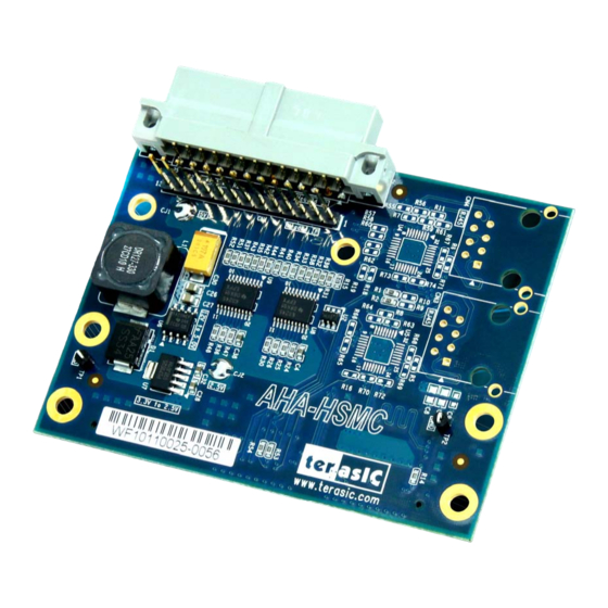
Chapter 2 AHA-HSMC Card Architecture This chapter provides information about architecture and block diagram of the AHA-HSMC card. Layout and Components Layout and Components The picture of the AHA-HSMC card is shown in Figure 2-1 Figure 2-2. It depicts the layout of... - Page 7 Figure 2-1 The AHA-HSMC Card PCB and component diagram (top view)
-
Page 8: Block Diagram Of The Isb Board
Block Diagram of the AHA Board Block Diagram of the AHA Board Figure 2-3 shows the block diagram of the AHA-HSMC card. The HSMC connector is housing all the wires from peripheral interfaces and makes direct connection to FPGA on the main board. - Page 9 Figure 2-3 Block Diagram of AHA-HSMC card...
-
Page 10: Chapter 3 Board Components
Chapter 3 Board Components HSMC Expansion Connector HSMC Expansion Connector The HSMC interface provides a mechanism to extend the peripheral set of an FPGA host board by means of a mezzanine card, which can address today’s high speed signaling requirement as well as standard or legacy low-speed device interface support. - Page 11 SENSOR_RST Output sensor reset VCC3P3 Power Power 3.3V VCC12 Power Power 12V IMG_DIN11 Input Pixel data (MSB) SHUTTER Output Shutter VCC3P3 Power Power 3.3V VCC12 Power Power 12V IMG_DIN10 Input Pixel data DEMO2_I2C_SCL Output Serial clock VCC3P3 Power Power 3.3V VCC12 Power Power 12V...
- Page 12 VCC12 Power Power 12V IMG_DIN5 Input Pixel data BUF_HISPI_DATA2_EN Output LVDS outputs enable VCC3P3 Power Power 3.3V VCC12 Power Power 12V IMG_DIN4 Input Pixel data BUF_HISPI_DATA3_EN Output LVDS outputs enable VCC3P3 Power Power 3.3V VCC12 Power Power 12V IMG_DIN1 Input Pixel data VCC3P3 Power...
-
Page 13: Aptina Parallel Port Interface
This section describes the Aptina Parallel Port interface on the AHA-HSMC. The AHA-HSMC contains an Aptina Parallel Port interface with a 26-pin header and a 13-pin header. The 26-pin header is the main connector that connects with Aptina image sensor headboard. - Page 14 SENSOR_SDA Input/Output Serial data SENSOR_SCL Input Serial clock Power Power 5V Power Power 5V CK_SENSOR_PIX Output Pixel clock Power Power GND Power Power GND CK_DEMO2 Power External clock for sensor Table 3-3 Pin assignments and descriptions for 13-pin header (Aptina Parallel) Pin Numbers Name Direction...
-
Page 15: Chapter 4 Demonstrations
The reference design is developed based on Altera Video and Image Processing Suite (VIP). A custom Camera VIP, provided by Terasic, is designed to retrieve raw image data from the image sensor and decode the raw data to RGB data. -
Page 16: Demonstration For Altera De2-115 Fpga Board
This section shows how to setup the video demo on the Altera DE2-115 using camera resolution 800x600. • Altera DE2-115 FPGA Board and USB Cable • Terasic AHA-HSMC Daughter Card • CMOS Image Sensor Headboard (MT9M023) • VGA Display and VGA Cable... - Page 17 Aptina headboard demonstration with DE2-115 FPGA board. Figure 4-2 Aptina image sensor demonstration hardware setup with DE2-115 Make sure the DE2-115 is powered off. Mount the AHA-HSMC daughter card onto the DE2-115 HSMC connector. Plug the Aptina headboard (MT9M023) to AHA-HSMC’s parallel connector.
-
Page 18: Demonstration For Cyclone Iii Development Board
Connect the power supply to the DE2-115 and turn on the DE2-115. Make sure Quartus 10.1 and NIOS II 10.1 are installed on your system. Copy the folder DE2-115-AHA-HSMC\demo_batch in the AHA-HSMC System CD onto your system and execute “test.bat”. - Page 19 Figure 4-3 Aptina image sensor demonstration hardware setup with Cyclone III development board 1. Make sure the Cyclone III development board is powered off. 2. Mount the AHA-HSMC daughter card onto the Cyclone III development board HSMC B connector. 3. Mount the DVI daughter card onto the Cyclone III development board HSMC A connector.
- Page 20 7. Connect the power supply to the Cyclone III development board and turn it on. 8. Make sure Quartus 10.1 and NIOS II 10.1 are installed on your system. 9. Copy the folder C3H-AHA\demo_batch in the AHA-HSMC System CD onto your system and execute “test.bat”.
-
Page 21: Chapter 5 Appendix
Initial Version (Preliminary) Copyright Statement Copyright Statement Copyright © 2011 Terasic Technologies. All rights reserved. Always visit AHA-HSMC webpage for new applications. We will be continuing providing interesting examples and labs on our AHA-HSMC webpage. Please visit www.altera.com aha.terasic.com for more information.
Need help?
Do you have a question about the AHA-HSMC and is the answer not in the manual?
Questions and answers