Table of Contents
Advertisement
Quick Links
Advertisement
Table of Contents

Related Manuals for Vimar 21126


Summary of Contents for Vimar 21126
- Page 1 Installer manual 21126 Electronic control with 8 inputs, 7 outputs, 3 modules.
-
Page 3: Table Of Contents
Contents 1. General description............................................4 2. Characteristics.............................................4 3. Connections..............................................4 3.1 Inputs...............................................4 3.2 Outputs..............................................7 4. RGB LEDs and pushbuttons........................................10 4.1 RGB LEDs ............................................10 4.2 Push buttons............................................10 5. Configuration of the device........................................11 5.1 Setting the colours of the LEDs......................................11 5.2 Device setup............................................11 5.3 Factory reset............................................12 6. -
Page 4: General Description
General description - Characteristics - Connections 1. General description Electronic control with 6 independent pushbuttons, 8 non-polarised inputs, 7 solid state outputs for non-polarised contacts, configurable RGB LED backlighting, 9-32 Vdc power supply, to be completed with Eikon Tactil labels and cover plate - 3 modules. 2. - Page 5 The inputs are not polarised and are isolated from the device's supply voltage by functional isolation (non-reinforced); this allows the connection of input signals with reference voltages that differ from the supply voltage of the 21126 control, provided they have SELV power supplies.
- Page 6 –V Example 3: Connection with a signal generator with different voltage references. The inputs can be connected directly to a third-party device that provides an output with voltage and current values compatible with the inputs of the 21126 control. The inputs common is to be connected directly to the negative (-) of the power supply of the third-party device.
-
Page 7: Outputs
Connections 3.2 Outputs The outputs connector is of the type JST PHR-9. 30 cm The outputs are non-polarised solid state (volt-free contact) and are all referred to the common on pin 9. The outputs can be used to control signals but are not suitable for controlling loads (for example, thee coils of large relays or contactors, high-power LED lights, etc.). •... - Page 8 The outputs are not polarised and are isolated from the device's supply voltage by functional isolation (non-reinforced); this allows the connection of output signals with reference voltages that differ from the supply voltage of the 21126 control, provided they have SELV power supplies.
- Page 9 Example 2: Connection of small indicator lights. The outputs can be connected to indicator lights with characteristics compatible with the maximum voltage and current values of the 21126 control. The outputs common is to be connected directly to the power supply positive (+).
-
Page 10: Rgb Leds And Pushbuttons
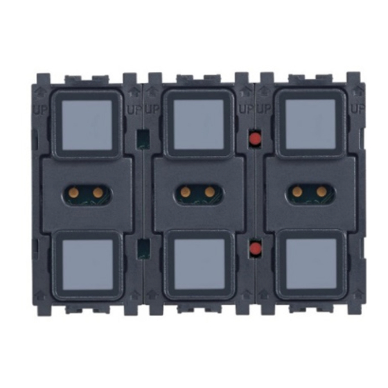
4.2 Pushbuttons When the cover plate is not fitted, the 21126 control presents six physical pushbuttons (shown in blue) and two configuration pushbuttons (shown in red). Once the cover plate has been fitted to the control, the 6 touchscreen buttons (shown in blue) can be used independently of each other. -
Page 11: Configuration Of The Device
Device configuration 5. Device configuration Caution: all the procedures described below musty be carried out using the physical pushbuttons, and therefore without the cover plate fitted to the device. 5.1 Setting the colours of the LEDs The colours of the LEDs can be configured in two different ways: - via signal on input 7;... - Page 12 Device configuration The illumination of the LEDs corresponds to a precise function, as shown in the following table: Left module Central module Right module High sensitivity Upper pushbutton Always off LED brightness in standby (default value) Lower pushbutton Always off Low sensitivity LED brightness in standby •...
-
Page 13: Factory Reset
The operating mode is selected by activating or not activating input 8; if the input is activated, feedback is enabled, otherwise feedback is disabled. 6.1 Display of load status (feedback enabled) This mode is useful in cases where a third-party system controls illumination of the LEDs on the 21126 control; normally the device is in standby condition. 6.1.1 Standby The brightness level of the six LEDs is that set during the "Standard setup"... -
Page 14: Installation Rules
Installation rules - Regulatory compliance 7. Installation rules Installation should be carried out by qualified personnel in compliance with the current regulations regarding the installation of electrical equipment in the country where the products are installed. 8. Regulatory compliance EMC Directive. Standard EN 60669-2-1. - Page 15 Viale Vicenza 14 36063 Marostica VI - Italy 21126IEN 02 1901 www.vimar.com...
Need help?
Do you have a question about the 21126 and is the answer not in the manual?
Questions and answers