
Subscribe to Our Youtube Channel
Related Manuals for Weller WP 65


Summary of Contents for Weller WP 65
- Page 1 Weller WP 65 Lötkolben Betriebsanleitung PK Elektronik Vertriebs GmbH, E-Mail: info@pkelektronik.com, Internet: www.pkelektronik.com...
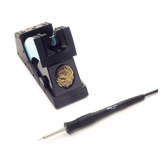
- Page 2 WP 65 WP 65 Lötkolben Geräteübersicht WP 65 WDH 10 Reinigungseinsatz Temperaturbeständige antistatische Silikonleitung Lötspitze Veriegelbarer Anschlussstecker Spitzenhülse PK Elektronik Vertriebs GmbH, E-Mail: info@pkelektronik.com, Internet: www.pkelektronik.com...
-
Page 3: Table Of Contents
Qualitätsanforderungen zugrunde gelegt, die eine einwandfreie Funktion des Gerätes sicherstellen. Diese Anleitung enthält wichtige Informationen, um den Lötkolben WP 65 sicher und sachgerecht in Betrieb zu nehmen, zu bedienen, zu warten und einfache Störungen selbst zu beseitigen. Lesen Sie diese Anleitung und die beiliegenden Sicherheitshinweise vor Inbetriebnahme des Lötkolbens... - Page 4 Verwendung des Werkzeugs oder unerlaubten Veränderungen am Gerät entstehen. Beachten Sie bitte Folgendes: Allgemeine − Legen Sie den Lötkolben WP 65 immer in die vorgesehene Hinweise Sicherheitsablage. − Entfernen Sie alle entzündbaren Objekte aus der Nähe des heißen Lötwerkzeugs.
-
Page 5: Lieferumfang
WP 65 Bestimmungsgemäßer Gebrauch Verwenden Sie den WP 65 Lötkolben ausschließlich für den in der Betriebsanleitung bezüglich Lösen, Verstauung und Ablage von elektronischen Bauteilen angegebenen Zweck unter den hier beschriebenen Bedingungen. Der bestimmungsgemäße Gebrauch des Lötkolbens WP 65 beinhaltet auch, dass −... -
Page 6: Inbetriebnahme Des Gerätes
Bei Berührung der Spitzen besteht Verbrennungsgefahr. Berühren Sie nicht die Lötspitzen und halten Sie entzündbare Objekte fern. 1. Den Lötkolben WP 65 vorsichtig auspacken. 2. Den Lötkolben in der Sicherheitsablage WDH 10 ablegen. 3. Den Anschlussstecker (5) an der Versorgungseinheit anschließen und durch Drehen im Uhrzeigersinn verriegeln. -
Page 7: Zubehör
6. Netzschalter der Versorgungseinheit einschalten und die gewünschte Temperatur einstellen. 7 Zubehör XNT Lötspitzen für den Lötkolben WP 65 Siehe Tabelle XNT Lötspitzen für Lötkolben WP 65 am Ende dieser Anleitung und auf www.weller-tools.com Ersatzteile und Zubehör für WP 65 Bestell-Nr. -
Page 8: Entsorgung
WP 65 8 Entsorgung Entsorgen Sie ausgetauschte Geräteteile, Filter oder alte Geräte gemäß den Vorschriften Ihres Landes. 9 Garantie Die Mängelansprüche des Käufers verjähren nach einem Jahr ab Ablieferung an ihn. Dies gilt nicht für Rückgriffsansprüche des Käufers nach §§ 478, 479 BGB. - Page 9 WP 65 Operating Instructions PK Elektronik Vertriebs GmbH, E-Mail: info@pkelektronik.com, Internet: www.pkelektronik.com...
- Page 10 WP 65 WP 65 Hardware Overview WP 65 WDH 10 Cleaning element Heat-resistant antistatic silicon cable Soldering tip Lockable connector plug Barrel PK Elektronik Vertriebs GmbH, E-Mail: info@pkelektronik.com, Internet: www.pkelektronik.com...
- Page 11 These instructions contain important information which will help you to start up, operate and service the WP 65 soldering iron safely and correctly as well as to eliminate simple faults or malfunctions yourselves.
- Page 12 WP 65 − Always pass on the WP 65 soldering iron to third parties together with these operating instructions. − The manufacturer accepts no liability for improper use of the tool or for unauthorised modifications. Please observe the following guidelines: General −...
-
Page 13: Included In Delivery
The WP 65 can only be switched to Standby or OFF mode using an optional switching holder. For directions for setting the standby temperature and the switching times, please refer to the operating instructions of the supply unit in use. -
Page 14: Commissioning The Device
Do not touch the hot soldering tips and keep them away from inflammable objects. 1. Carefully unpack the WP 65 soldering iron. 2. Place the soldering iron into safety rest WDH 10. 3. Insert the connecting plug (5) into the power supply socket and lock it by turning it clockwise. -
Page 15: Accessories
6. Switch on the supply unit and set the required temperature. 7 Accessories XNT soldering tips for the WP 65 soldering iron See the table XNT soldering tips for WP 65 soldering iron in the section in the back and at www.weller-tools.com. Replacement parts and accessories for WP 65 Order no. -
Page 16: Disposal
Use of non-Weller Tools components will void this warranty if a non-Weller Tools component is defective (or is the source of the defect). Weller Tools will repair or replace products found to be defective not caused by a part, component or accessory manufactured by another company, during the warranty period. - Page 17 WP 65 Manual de uso PK Elektronik Vertriebs GmbH, E-Mail: info@pkelektronik.com, Internet: www.pkelektronik.com...
- Page 18 WP 65 WP 65 Componentes principales del aparato WDH 10 WP 65 Limpiador Cable de silicona antiestático y termorresistente Punta de soldadura Clavija de conexión con mecanismo de bloqueo Casquillo de sujeción PK Elektronik Vertriebs GmbH, E-Mail: info@pkelektronik.com, Internet: www.pkelektronik.com...
-
Page 19: Acerca De Estas Instrucciones
Directivas que tener en cuenta El lápiz de soldadura WP 65 de Weller dispone de la Declaración de Conformidad CE que certifica el cumplimiento de los requisitos básicos de seguridad contemplados en las Directivas 2004/108/CE y 2006/95/CE. - Page 20 Tener en cuenta lo siguiente: Indicaciones − Colocar siempre el lápiz de soldadura WP 65 en el soporte de generales seguridad previsto a tal efecto. − Retirar todos los objetos inflamables de las proximidades de la herramienta de soldadura.
-
Page 21: Piezas Suministradas
4 Descripción del aparato Lápiz de soldadura WP 65 El lápiz de soldadura WP 65 se distingue por su gran rapidez y precisión para alcanzar la temperatura deseada. La extraordinaria potencia (65 W) de su elemento calefactor le proporciona un comportamiento dinámico excelente. -
Page 22: Puesta En Servicio Del Aparato
No toque las puntas de soldadura calientes y manténgalas siempre alejadas de objetos inflamables. 1. Desembalar con cuidado el lápiz de soldadura WP 65. 2. Colocar el lápiz de soldadura en el soporte de seguridad WDH 10. 3. Insertar la clavija de conexión (5) en la unidad de alimentación corriente y bloquearla girándola en sentido horario. -
Page 23: Cambio De Las Puntas De Soldadura Wp 65
WP 65 6 Cambio de las puntas de soldadura WP 65 ¡ADVERTENCIA! Riesgo de quemaduras La punta de soldadura alcanza temperaturas muy elevadas durante la soldadura y desoldadura. Existe riesgo de quemaduras al tocar la punta de soldadura . La herramienta de soldadura debe permanecer desconectada en el soporte de seguridad (WDH 10) por lo menos durante 3 min. -
Page 24: Accesorios
Puntas de soldadura XNT para el lápiz de soldadura WP 65 Ver la tabla de puntas de soldadura XNT para lápiz de soldadura WP 65 al final de este manual y en www.weller-tools.com. Piezas de repuesto y accesorios para el WP65 N.º pedido Descripción... - Page 25 WP 65 Soldering Tips XNT soldering tips for WP 65 Model Type Width A Order no. description inch XNT 1 Round tip 0.0197 005 44 850 99 ∅ ∅ Length: 27 mm XNT 1S Round slim tip 0.0079 005 44 852 99 ∅...
- Page 26 WP 65 Exploded Drawing PK Elektronik Vertriebs GmbH, E-Mail: info@pkelektronik.com, Internet: www.pkelektronik.com...
Need help?
Do you have a question about the WP 65 and is the answer not in the manual?
Questions and answers