Advertisement
Quick Links
ASSEMBLY INSTRUCTIONS
Thanks for purchasing one of our products.
Please read carefully the assembly instructions before the installation.
Do not discard this manual or the packaging material until the unit has
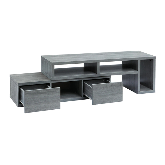
MODEL RTA-7050
REQUIRES OF
2 PERSONS
been completely assembled.
Expandable and Reversible
Imported by:
Advertisement

Subscribe to Our Youtube Channel
Related Manuals for Techni Mobili RTA-7050


Summary of Contents for Techni Mobili RTA-7050
- Page 1 MODEL RTA-7050 ASSEMBLY INSTRUCTIONS REQUIRES OF 2 PERSONS Thanks for purchasing one of our products. Please read carefully the assembly instructions before the installation. Do not discard this manual or the packaging material until the unit has been completely assembled.
-
Page 2: Main Parts List
RTA-7050 MAIN PARTS LIST ❶ ❸ ❹ ❷ Middle panel for Short vertical panel Long exterior vertical Top panel for upper upper section for upper section section panel for upper section ❺ ❼ ❽ ❻ Long interior Bottom panel for... -
Page 3: Screws List
RTA-7050 MAIN PARTS LAYOUT (for reference) ❶ ❸ ❼ ❸ ❷ ⓮ ⓬ ⓮ ❽ ❺ ❹ ❾ ❻ SCREWS LIST Figure Size qty. Figure Size Qty. M6x35mm St3x14mm ⌀25 (felt) ⌀8x30mm ⌀22 (laminate) St7x58mm St3.5x40mm ☛ This unit uses special cam bolts and locks. The following explains how to assemble using this kind of hardware. - Page 4 RTA-7050 BEFORE STARTING THE ASSEMBLY, PLEASE READ THE FOLLOWING TIPS AND WARNING: • Do a quick inventory to make sure the product contains all the parts and hardware. • Missing, damaged and defective parts can be replaced at no cost to you. Please refer to the CONTACT card included with the product.
- Page 5 RTA-7050 STEPS 1 THROUGH 11 IS FOR THE ASSEMBLY OF THE LOWER SECTION Separate all the sliders pieces ⑲ according to their shape (no assembly is done here): STEP 1 - The “Flat” ones go on the side panels and will be used on step 2.
- Page 6 RTA-7050 STEP 4 Insert the back panel ⑬ thru the groves of panels ⑦, ⑨ and ⑩. 1st: Insert the wooden pins Ⓑ in the corresponding holes on panels ⑨, ⑩, ⑪ and ⑫. STEP 5 2nd: With the help of another person, place the bottom panel ⑧ and assemble it to panels ⑨, ⑩, ⑪...
-
Page 7: Very Important
RTA-7050 STEP 7 Assemble the drawer back panel ⑰ to the side STEP 8 panels ⑮ and ⑯ using screws Ⓓ as shown. Screws: Insert the drawer bottom panel ⑱ thru the groves of side panels ⑮, ⑯ and ST3.5x40 ��... - Page 8 RTA-7050 STEP 11 Insert the drawers in the unit. If they don’t seem to fit, review steps 2 and 10 for the correct assembly of the sliders. STEPS 12 THROUGH 18 FOR THE ASSEMBLY OF THE UPPER SECTION STEP 12 1st: Insert the wooden pins Ⓑ...
- Page 9 RTA-7050 STEP 13 1st: Insert the wooden pins Ⓑ in the corresponding holes on panel ②. 2nd: Insert the bolts Ⓐ in the corresponding holes on panel ⑤. Screws: 3rd: Insert and align the cam locks Ⓐ in panel ②.
- Page 10 P.10 P.10 RTA-7050 1st: Assemble the panel ② to the panels ③ using screws Ⓒ. STEP 15 2nd: Insert the wooden pins Ⓑ in the corresponding holes on panel ①. 3rd: Insert the bolts Ⓐ in the corresponding holes on panel ①.
- Page 11 P.11 P.11 RTA-7050 STEP 17 Place the following adhesive lables: - Felt Ⓕ for the screw holes on panel ⑥. Screws: - Laminate Ⓖ for the cam lock holes on panels ③, ④ and ⑤. Φ25 (felt) �� (Felt) Φ22 ��...
-
Page 12: Weight Limits
P.12 P.12 RTA-7050 AFTER THE ASSEMBLY IS DONE, PLEASE READ CAREFULLY THE FOLLOWING CARE AND MAINTENANCE WARNINGS: WEIGHT LIMITS: 44 Lbs (20 Kg) 55 Lbs (25 Kg) expanded 88 Lbs (40 Kg) closed 88 Lbs (40 Kg) 11 Lbs (5 kg)
Need help?
Do you have a question about the RTA-7050 and is the answer not in the manual?
Questions and answers