Table of Contents
Advertisement
Available languages
Available languages
Quick Links
Advertisement
Chapters
Table of Contents

Related Manuals for Minebea Intec MP 90/04


Summary of Contents for Minebea Intec MP 90/04
- Page 1 Installation Manual Cable Junction Box MP 90/04 Translation of the Original Installation Manual 9499 053 90401 Edition 3.1.0 09/26/2017 Minebea Intec GmbH, Meiendorfer Str. 205 A, 22145 Hamburg, Germany Phone: +49.40.67960.303 Fax: +49.40.67960.383...
- Page 2 Any information in this document is subject to change without notice and does not represent a commitment on the part of Minebea Intec unless legally prescribed. This product should be operated/installed only by trained and qualified personnel. In correspondence concerning this product, the type, name, and release number/serial number as well as all license numbers relating to the product have to be cited.
-
Page 3: Table Of Contents
Cable Junction Box MP 90/04 Table of contents Table of contents Introduction............................3 Read the manual................................. 3 This is what instructions look like..........................3 This is what lists look like............................3 This is what menus and soft keys look like ......................3 This is what safety instructions look like......................... - Page 4 Cable Junction Box MP 90/04 Table of contents Cleaning ..................................18 Disposal ............................. 19 Minebea Intec EN-2...
-
Page 5: Introduction
1 Introduction Cable Junction Box MP 90/04 Introduction Read the manual Please read this manual carefully and completely before using the product. This manual is part of the product. Keep it in a safe and easily accessible location. This is what instructions look like 1. -
Page 6: Hotline
Cable Junction Box MP 90/04 1 Introduction NOTICE Warning of property and/or environmental damage. ATTENTION indicates that damage to property and/or the environment may occur if appropriate safety measures are not observed. Take appropriate safety measures. Note: User tips, useful information and notes. -
Page 7: Safety Instructions
2 Safety instructions Cable Junction Box MP 90/04 Safety instructions General notes CAUTION Warning of personal injury. The product was in perfect condition with regard to safety features when it left the factory. To maintain this condition and to ensure safe operation, the user must follow the instructions and observe the warnings in this manual. -
Page 8: Incoming Goods Inspection
General information Repairs are subject to inspection and must be carried out at Minebea Intec. In case of defect or malfunction, please contact your local Minebea Intec dealer or service center for repair. When returning the device for repair, please include a precise and complete description of the problem. -
Page 9: Specifications
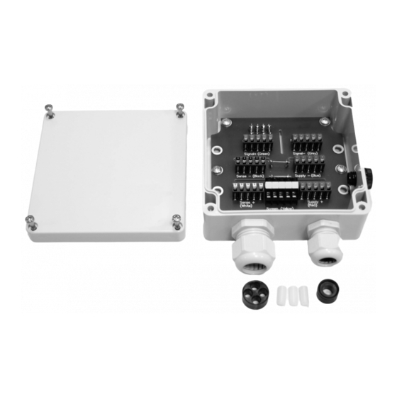
3 Specifications Cable Junction Box MP 90/04 Specifications Equipment supplied Description Cover Box incl. electronics Jumpers for corner correction resistors Pressure compensation element Cable gland M20 Reduction sealing ring M20 (for ≤8 mm) Locking pin 6 mm (3×) 4-seal insert M25... -
Page 10: Technical Data
Cable Junction Box MP 90/04 3 Specifications Technical Data Protection classes per DIN EN 60529 IP65: Dust-proof and leak-proof against water jets (nozzle) from any angle. Installation position Cable entry from below Quantity of load cells 1…4 Pressure equalization Plastic pressure equalization element... -
Page 11: Dimensions
3 Specifications Cable Junction Box MP 90/04 Dimensions all dimensions in mm EN-9 Minebea Intec... -
Page 12: Installation And Connection Information
Cable Junction Box MP 90/04 4 Installation and connection information 4 Installation and connection information General information Only use the cable glands provided by the manufacturer. Install the junction box so that the cable glands are on the bottom. Do not open the junction box when connected to the voltage supply. -
Page 13: Cable Gland
4 Installation and connection information Cable Junction Box MP 90/04 Terminal contact - sense (connection cable) Sense + white Terminal contacts + sense (load cells) 1–4 Terminal contact + sense (connection cable) Supply + Terminal contacts + supply voltage (load cells) 1–4... -
Page 14: 4.4 Attaching The Cable Gland
Cable Junction Box MP 90/04 4 Installation and connection information 4.4 Attaching the cable gland Remove the parts from the packaging. 2. Screw the cable gland (2) into the cable junction box and tighten at the hex. Note: It is essential that the following tightening torques are observed:... -
Page 15: Fitting The Reduction Sealing Ring/4-Seal Insert
4 Installation and connection information Cable Junction Box MP 90/04 Fitting the reduction sealing ring/4-seal insert Unscrew the cap nuts (2). 2. Remove the existing sealing ring from the metal sleeve (3). 3. Insert the reduction sealing ring (1) in the M20 cable gland (for cables ≤8 mm). -
Page 16: Cable Connections
Cable Junction Box MP 90/04 5 Cable connections Cable connections General information In order to use the junction boxes for load cells with 6-wire cables, jumpers 1 and 2 must be opened; see Chapter 4.2. Cable entry must be from below. -
Page 17: Equipotential Bonding Conductor
5 Cable connections Cable Junction Box MP 90/04 Equipotential bonding conductor NOTICE It is especially important that the ground is connected correctly to the components and the cable junction box. You must also ground the device separately and ensure the power supply is properly shielded against the effects of lightning. -
Page 18: Electronic Corner Correction
Electronic corner correction 5.5.1 General information Minebea Intec load cells are produced according to high quality standards and have precisely adjusted output values. Nonetheless, mechanical imbalances can cause impermissible corner load errors to arise, which will need to be offset by soldering in resistors. -
Page 19: Procedure
5 Cable connections Cable Junction Box MP 90/04 NOTICE Loss of calibration accuracy An unstable signal can arise due to contact problems. This results in fluctuating zero points, which lead to the loss of calibration accuracy. Do not use a potentiometer. -
Page 20: Maintenance/Repairs/Soldering Work/Cleaning
Repairs Repairs are subject to inspection and must be carried out at Minebea Intec. In case of defect or malfunction, please contact your local Minebea Intec dealer or service center for repair. When returning the device for repair, please include a precise and complete description of the problem. - Page 21 7 Disposal Cable Junction Box MP 90/04 Disposal If the packaging is no longer required, please take it to your local waste disposal facility and/or a reputable disposal company or collection point. The packaging largely consists of environmentally friendly materials which can be used as secondary raw materials.
- Page 22 Published by Minebea Intec GmbH | Meiendorfer Strasse 205 A | 22145 Hamburg, Germany Phone: +49.40.67960.303 | Email: info@minebea-intec.com www.minebea-intec.com...
- Page 23 Installationshandbuch Kabelverbindungskasten MP 90/04 Originalinstallationshandbuch 9499 053 90401 Ausgabe 3.1.0 26.09.2017 Minebea Intec GmbH, Meiendorfer Str. 205 A, 22145 Hamburg, Deutschland Tel.: +49.40.67960.303 Fax: +49.40.67960.383...
- Page 24 Vorwort Unbedingt beachten! Alle Angaben in diesem Dokument sind - soweit nicht gesetzlich vorgegeben - unverbindlich für Minebea Intec und stehen unter Änderungsvorbehalt. Die Bedienung/Installation des Produktes darf nur von geschultem, fach- und sachkundigem Personal durchgeführt werden. Bei Schriftwechsel über dieses Produkt bitte Typ, Bezeichnung und Versionsnummer/Seriennummer sowie alle mit dem Produkt in Zusammenhang stehenden Lizenznummern angeben.
- Page 25 Kabelverbindungskasten MP 90/04 Inhaltsverzeichnis Inhaltsverzeichnis Einleitung ............................3 Lesen Sie das Handbuch............................3 So sehen Handlungsanweisungen aus........................3 So sehen Listen aus ..............................3 So sehen Menüs und Softkeys aus........................... 3 So sehen Sicherheitshinweise aus ........................... 3 Hotline ..................................4 Sicherheitshinweise ..........................
- Page 26 Kabelverbindungskasten MP 90/04 Inhaltsverzeichnis Reinigung................................... 18 Entsorgung ............................19 Minebea Intec DE-2...
-
Page 27: Einleitung
1 Einleitung Kabelverbindungskasten MP 90/04 Einleitung Lesen Sie das Handbuch Lesen Sie das Handbuch aufmerksam und vollständig durch, bevor Sie mit dem Produkt arbeiten. Dieses Handbuch ist Teil des Produktes. Bewahren Sie es gut erreichbar und sicher auf. So sehen Handlungsanweisungen aus 1. -
Page 28: Hotline
Kabelverbindungskasten MP 90/04 1 Einleitung VORSICHT Warnung vor Personenschäden. VORSICHT vor möglicher eintretender Situation mit leichten, reversiblen Verletzungen als Folge, wenn die entsprechenden Vorsichtsmaßnahmen nicht getroffen werden. Entsprechende Vorsichtsmaßnahmen ergreifen. ACHTUNG Warnung vor Sach- und/oder Umweltschäden. ACHTUNG vor möglicher eintretender Situation mit Sach- und/oder Umweltschäden als Folge, wenn die entsprechenden Vorsichtsmaßnahmen nicht getroffen werden. -
Page 29: Sicherheitshinweise
2 Sicherheitshinweise Kabelverbindungskasten MP 90/04 Sicherheitshinweise Allgemeine Hinweise VORSICHT Warnung vor Personenschäden. Das Produkt hat das Werk in sicherheitstechnisch einwandfreiem Zustand verlassen. Um diesen Zustand zu erhalten und einen gefahrlosen Betrieb sicherzustellen, muss der Anwender die Hinweise und Warnvermerke dieser Dokumentation befolgen. -
Page 30: Wareneingangskontrolle
Reparatur und Wartung 2.5.1 Allgemeine Hinweise Reparaturen sind prüfpflichtig und können nur bei Minebea Intec durchgeführt werden. Bei einem Defekt oder einer Funktionsstörung bitte an die lokale Vertretung von Minebea Intec wenden, um Reparaturmaßnahmen einzuleiten. Das Gerät muss mit exakter und kompletter Fehlerbeschreibung zur Reparatur eingeschickt werden. -
Page 31: Spezifikation
3 Spezifikation Kabelverbindungskasten MP 90/04 Spezifikation Lieferumfang Pos. Bezeichnung Deckel Kasten inkl. Elektronik Brücken für die Eckenabgleichwiderstände Druckausgleichselement Kabelverschraubung M20 Reduzier-Dichtring M20 (für ≤8 mm) Verschlussstift 6 mm (3×) 4-fach Dichteinsatz M25 Kabelverschraubung M25 Folgende Positionen sind ohne Abbildung: Bohrschablone... -
Page 32: Technische Daten
Kabelverbindungskasten MP 90/04 3 Spezifikation Technische Daten Schutzarten gemäß DIN EN 60529 IP65: Staubdicht und geschützt gegen Eindringen von Strahlwasser (Düse) aus beliebigem Winkel. Einbaulage Kabeleinführung von unten Anzahl Wägezellen 1…4 Druckausgleich Kunststoff-Druckausgleichselement Werkstoff des Verbindungskastens Farbe des Verbindungskastens grau, ähnlich RAL 7035... -
Page 33: Abmessungen
3 Spezifikation Kabelverbindungskasten MP 90/04 Abmessungen alle Abmessungen in mm DE-9 Minebea Intec... -
Page 34: Montage- Und Anschlusshinweise
Kabelverbindungskasten MP 90/04 4 Montage- und Anschlusshinweise 4 Montage- und Anschlusshinweise Allgemeine Hinweise Nur die vom Hersteller gelieferten Kabelverschraubungen verwenden. Den Verbindungskasten so montieren, dass sich die Kabelverschraubungen unten befinden. Den Verbindungskasten nicht öffnen, wenn eine Spannung anliegt. Hinweis: Bei Umgebungstemperaturen >45°C müssen Kabel verwendet werden, die für mindestens 85°C geeignet sind. -
Page 35: Kabeldurchführung
4 Montage- und Anschlusshinweise Kabelverbindungskasten MP 90/04 Sense + weiß Klemmkontakte + Sense Wägezellen 1…4 Klemmkontakt IND + Sense Verbindungskabel Supply + Klemmkontakte + Speisespannung Wägezellen 1…4 Klemmkontakt IND + Speisespannung Verbindungskabel Screen gelb Klemmkontakte Schirm Wägezellen 1…4 Klemmkontakt IND Schirm Verbindungskabel Brücke... -
Page 36: 4.4 Kabelverschraubung Montieren
Kabelverbindungskasten MP 90/04 4 Montage- und Anschlusshinweise 4.4 Kabelverschraubung montieren Die Einzelteile dem Beipack entnehmen. 2. Stopfbuchse (2) in den Kabelverbindungskasten einschrauben und am Sechskant festziehen. Hinweis: Die folgenden Anzugsmomente unbedingt beachten: M20: 4 Nm M25: 6 Nm 3. Überwurfmutter (1) auf die Stopfbuchse schrauben und leicht anziehen. -
Page 37: Reduzier-Dichtring/4-Fach Dichteinsatz Montieren
4 Montage- und Anschlusshinweise Kabelverbindungskasten MP 90/04 Reduzier-Dichtring/4-fach Dichteinsatz montieren Überwurfmutter (2) abschrauben. 2. Vorhandenen Dichtring aus der Stopfbuchse (3) entfernen. 3. Bei der M20-Verschraubung den Reduzier-Dichtring (1) einsetzen (bei Kabel ≤8 mm). Hinweis: Unbedingt die Seite mit der Dichtlippe zuerst in die Stopfbuchse einsetzen! 4. -
Page 38: Kabelverbindungen
Kabelverbindungskasten MP 90/04 5 Kabelverbindungen Kabelverbindungen Allgemeine Hinweise Um den Verbindungskasten für Wägezellen mit 6-Leiter-Kabel einsetzen zu können, müssen die Drahtbrücken 1 und 2 geöffnet werden, siehe Kapitel 4.2. Die Kabeleinführung muss von unten erfolgen. Die Adern und die Abschirmung des Verbindungskabels mit Aderendhülsen nach... -
Page 39: Potenzialausgleich
5 Kabelverbindungen Kabelverbindungskasten MP 90/04 Potenzialausgleich ACHTUNG Der korrekte Anschluss der Erde an die Einbauteile und an den Kabelverbindungskasten ist besonders wichtig. Auf eine zusätzliche separate Erdung des Gerätes sowie eine genügende Absicherung des Stromnetzes gegen Blitzrückwirkung darf keinesfalls verzichtet werden. Der einfache Anschluss des Schutzleiters genügt nicht! -
Page 40: Elektrischer Eckenabgleich
5 Kabelverbindungen Elektrischer Eckenabgleich 5.5.1 Allgemeine Hinweise Wägezellen von Minebea Intec werden nach hohen Qualitätsmaßstäben gefertigt und verfügen über sehr genau abgeglichene Ausgangswerte. Dennoch können durch mechanische Unsymmetrien unzulässige Eckenlastfehler auftreten, die durch das Einlöten von Widerständen ausgeglichen werden müssen. -
Page 41: Vorgehensweise
5 Kabelverbindungen Kabelverbindungskasten MP 90/04 ACHTUNG Verlust der Eichgenauigkeit Ein instabiles Signal kann durch Kontaktprobleme entstehen. Die Folge sind wandernde Nullpunkte, die zum Verlust der Eichgenauigkeit führen. Keine Potenziometer verwenden. Nur Widerstände von 0…5,62 Ω (1%, P70 = 0,6 W) der Baugröße MBB0207 (ca. -
Page 42: Wartung/Reparatur/Lötarbeiten/Reinigung
Fachkraft ausgeführt werden, die damit verbundene Gefahren kennt. Reparatur Reparaturen sind prüfpflichtig und können nur bei Minebea Intec durchgeführt werden. Bei einem Defekt oder einer Funktionsstörung bitte an die lokale Vertretung von Minebea Intec wenden, um Reparaturmaßnahmen einzuleiten. - Page 43 7 Entsorgung Kabelverbindungskasten MP 90/04 Entsorgung Wird die Verpackung nicht mehr benötigt, ist diese der örtlichen Abfallentsorgung, bzw. einem anerkanntem Entsorger oder einer Sammelstelle zuzuführen. Die Verpackung besteht zu einem Großteil aus umweltfreundlichen Materialien, die als Sekundärrohstoffe dienen können. Dieses Produkt darf nicht – auch nicht von Kleingewerbetreibenden – in den Hausmüll oder an Sammelstellen der örtlichen öffentlichen Entsorgungsbetriebe abgegeben...
- Page 44 Published by Minebea Intec GmbH | Meiendorfer Strasse 205 A | 22145 Hamburg, Germany Phone: +49.40.67960.303 | Email: info@minebea-intec.com www.minebea-intec.com...
- Page 45 Manuel d’installation Boîte de jonction MP 90/04 Traduction du manuel d'installation original 9499 053 90401 Édition 3.1.0 26/09/2017 Minebea Intec GmbH, Meiendorfer Str. 205 A, 22145 Hambourg, Allemagne Tél : +49.40.67960.303 Fax: +49.40.67960.383...
- Page 46 Toutes les informations contenues dans ce document sont sujettes à modification sans préavis et ne constituent en aucun cas un engagement de la part de Minebea Intec, sauf prescription légale contraire. Seuls les membres du personnel qualifiés ayant reçu la formation correspondante sont autorisés à utiliser/installer ce produit. Dans toute correspondance concernant le produit, veuillez indiquer le type, le nom et le numéro de la version/numéro...
- Page 47 Boîte de jonction MP 90/04 Table des matières Table des matières Introduction............................3 Veuillez lire le manuel ..............................3 Typographie des actions à effectuer ........................3 Typographie des listes ............................... 3 Typographie des menus et des touches programmables..................3 Typographie des consignes de sécurité........................3 Hotline ..................................
- Page 48 Boîte de jonction MP 90/04 Table des matières Nettoyage .................................. 18 Elimination des équipements usagés....................19 Minebea Intec FR-2...
-
Page 49: Introduction
1 Introduction Boîte de jonction MP 90/04 Introduction Veuillez lire le manuel Lisez ce manuel avec attention et dans son intégralité avant d’utiliser le produit. Ce manuel fait partie du produit fourni. Conservez-le dans un lieu sûr et facile d’accès. -
Page 50: Hotline
Boîte de jonction MP 90/04 1 Introduction AVIS Avertissement contre le risque de dommages matériels et/ou à l’environnement. ATTENTION face à une situation susceptible de survenir et entraînant des dommages matériels et/ou des dommages pour l'environnement si les mesures de précaution correspondantes ne sont pas prises. -
Page 51: Consignes De Sécurité
2 Consignes de sécurité Boîte de jonction MP 90/04 Consignes de sécurité Remarques générales ATTENTION Avertissement contre un risque de blessures. Le produit est sorti d’usine dans un parfait état de sécurité technique. Pour maintenir cet état et assurer un fonctionnement sans danger, l’opérateur doit suivre les instructions et les consignes de sécurité... -
Page 52: Contrôle À La Réception
Minebea Intec. Si l’appareil est défectueux ou ne fonctionne pas correctement, veuillez vous adresser à votre représentant Minebea Intec qui se chargera des réparations nécessaires. L’appareil doit être renvoyé à l’usine pour réparation, avec une description exacte et complète du défaut. -
Page 53: Spécifications
3 Spécifications Boîte de jonction MP 90/04 Spécifications Contenu de la livraison Pos. Désignation Couvercle Boîtier et composants électroniques Ponts pour les résistances d’équilibrage des angles Composant de compensation de la pression Presse-étoupe M20 Bague étanche de réduction M20 (pour ≤8 mm) Obturateur 6 mm (3×) -
Page 54: Caractéristiques Techniques
Boîte de jonction MP 90/04 3 Spécifications Caractéristiques techniques Indices de protection selon EN 60529 IP65 : Étanche à la poussière et protégé contre la pénétration de jet d’eau (buse), quel que soit l’angle. Position de montage Introduction du câble par le bas Nombre de capteurs de pesage 1…4... -
Page 55: Dimensions
3 Spécifications Boîte de jonction MP 90/04 Dimensions Toutes les dimensions sont en mm. FR-9 Minebea Intec... -
Page 56: Instructions De Montage Et De Raccordement
Boîte de jonction MP 90/04 4 Instructions de montage et de raccordement 4 Instructions de montage et de raccordement Remarques générales Utiliser uniquement les presse-étoupes fournis. Monter la boîte de jonction afin que les presse-étoupes se trouvent en bas. Ne pas ouvrir la boîte de jonction lorsqu’il/elle est sous tension. -
Page 57: Passe-Câble
4 Instructions de montage et de raccordement Boîte de jonction MP 90/04 Contact de borne Sense - câble de connexion Sense + blanc Contacts de borne, Sense + capteurs de pesage 1 à 4 broches Contact de borne Sense + câble de connexion... -
Page 58: 4.4 Montage Du Presse-Étoupe
Boîte de jonction MP 90/04 4 Instructions de montage et de raccordement 4.4 Montage du presse-étoupe Sortir toutes les pièces de leur emballage. 2. Visser le presse-étoupe (2) dans le boîtier de raccordement des câbles et le serrer sur l’hexagone. - Page 59 4 Instructions de montage et de raccordement Boîte de jonction MP 90/04 Mise en place d’une bague étanche de réduction/d’une garniture d’étanchéité quadruple Dévisser l’écrou-raccord (2). 2. Retirer la bague d’étanchéité existante du presse-étoupe (3). 3. Avec le presse-étoupe M20, installer la bague étanche de réduction (1) (pour un câble de ≤8 mm).
-
Page 60: Raccordements Des Câbles
Boîte de jonction MP 90/04 5 Raccordements des câbles Raccordements des câbles Remarques générales Afin de pouvoir utiliser une boîte de jonction pour capteur de pesage avec câble à 6 fils, les cavaliers 1 et 2 doivent être ouverts. Voir chapitre 4.2. -
Page 61: Équipotentialité
5 Raccordements des câbles Boîte de jonction MP 90/04 Équipotentialité AVIS Vérifier que la mise à la terre des pièces et de la boîte de jonction est correctement effectuée. Veiller à la mise à la terre séparée de l’appareil et à la protection suffisante du réseau électrique contre la foudre. -
Page 62: Correction D'angle Électrique
Correction d’angle électrique 5.5.1 Remarques générales Les capteurs de pesage de Minebea Intec sont fabriqués selon les standards de qualité les plus élevés et disposent de valeurs de sortie extrêmement précises. Toutefois, des asymétries mécaniques peuvent entraîner des erreurs non autorisées de charges excentrées, lesquelles doivent être compensées par le brasage de résistances. -
Page 63: Manière De Procéder
5 Raccordements des câbles Boîte de jonction MP 90/04 AVIS Perte d’exactitude de l’étalon Un signal instable peut provenir de problèmes de contact. Il s’ensuit des points zéro variables, conduisant à la perte d’exactitude de l’étalon. Ne pas utiliser de potentiomètre. -
Page 64: Maintenance/Réparation/Travaux De Soudure/Nettoyage
Minebea Intec. Si l’appareil est défectueux ou ne fonctionne pas correctement, veuillez vous adresser à votre représentant Minebea Intec qui se chargera des réparations nécessaires. L’appareil doit être renvoyé à l’usine pour réparation, avec une description exacte et complète du défaut. - Page 65 7 Elimination des équipements usagés Boîte de jonction MP 90/04 Elimination des équipements usagés Si vous n'avez plus besoin de l'emballage, vous devez l'apporter au centre local de traitement des déchets, à une entreprise certifiée de recyclage et d'élimination des déchets ou à...
- Page 66 Published by Minebea Intec GmbH | Meiendorfer Strasse 205 A | 22145 Hamburg, Germany Phone: +49.40.67960.303 | Email: info@minebea-intec.com www.minebea-intec.com...
Need help?
Do you have a question about the MP 90/04 and is the answer not in the manual?
Questions and answers