
Related Manuals for Carlson Merlin LT


Summary of Contents for Carlson Merlin LT
- Page 1 Merlin LT Vessel-based LIDAR system user manual Merlin LT user manual H-0218-8000-01-B January 2020...
-
Page 3: Table Of Contents
Merlin diagnostic tool software ..............................14 Optional accessories .................................. 15 Installation ......................................16 Choosing a mounting location for the Merlin LT ......................... 16 Choosing an appropriate orientation ............................19 Lever arm offset measurement ..............................20 Lever arm offset measurement when using the mounting plate ....................23 Cable runs .................................... - Page 4 Maintenance and care of Merlin LT ..............................52 General ...................................... 52 Preventative maintenance ................................52 Mechanical drawings ................................... 53 Merlin LT positioned at 90° vertical angle........................... 53 Merlin LT positioned at 0°vertical angle ............................54 Laser safety ......................................55 10.1 Merlin LT laser module ................................
-
Page 5: Customer Information
1.1 Dear customer The Merlin LT system is designed to be easy to operate. However, we would ask you to take the time to read these operating instructions carefully before using the system, and to keep the manual with the instrument at all times. - Page 6 Installation of the Merlin LT system must be performed only by trained personnel. • • Changing the Merlin LT port and IP addresses must be carried out using only the Merlin diagnostic tool software by appropriately trained personnel. Disconnect power before performing any maintenance operations.
-
Page 7: Introduction
(IMU), global navigation satellite system (GNSS) receivers, and industry-standard hydrographic acquisition software packages. The Merlin LT is designed to be lighter-weight, and of a smaller footprint, than the standard Merlin system, while the capabilities of the laser remain the same. -
Page 8: Equipment Description
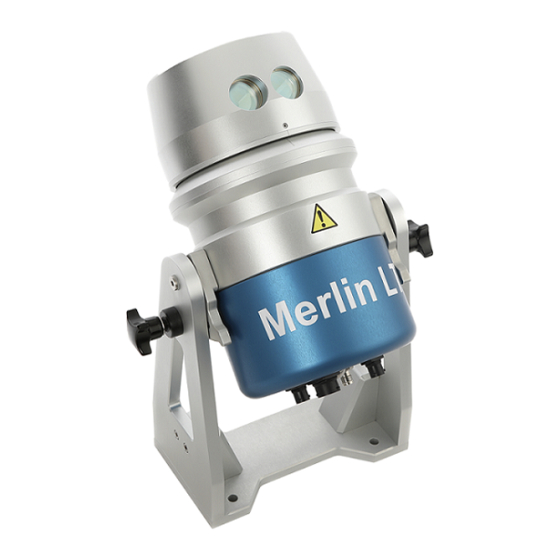
The sections below describe each individual hardware element of a standard Merlin LT vessel-based lidar system. 3.1 Merlin LT The Merlin LT unit incorporates a rotating laser range finder which is housed with a motor and encoder in a weather- proof pod, held between two ‘A-frame’ pillars that sit on a base plate. - Page 9 3.1.2 A-frame and base plate The pod can rotate vertically around the vertical pivot at the top of the A-Frame. The fixed angles are 90° (horizontal), 45° and 0° (vertically up). Figure 2 Merlin positioned vertically at 90°, 45° and 0° Vertical locking stud A-frame...
- Page 10 Use the four holes in the base plate to secure the Merlin LT directly to a mounting point on a vessel. Alternatively, use the base plate to secure the Merlin LT to the mounting plate (see section 3.6.1).
-
Page 11: Cables
The Ethernet cable provides communication between the Merlin LT and the vessel’s main PC running navigation software. The Cat 6 Ethernet cable attaches to the back of the Merlin LT with a four-pin female Souriau connector. The standard RJ45 connector connects to the PC. - Page 12 The serial cable delivers ZDA timing messages from an external timing source to the Merlin LT unit. The serial cable attaches to the back of the Merlin LT via a three-pin male Souriau connector. The 9-way D-type connector on the other end connects to the source of the ZDA output.
-
Page 13: Transit Case
Figure 9 Power cable The power cable attaches to the back of the Merlin LT via a four-pin female Souriau connector. On the other end are ring-crimp connectors which connect to a dc power supply of voltage range 12 V dc. -
Page 14: Usb Drive
The Merlin diagnostic tool software is a simple application which allows the set-up and configuration of the Merlin LT system. It is loaded on the USB stick that is supplied in the Merlin LT transit case. Plug the USB stick into the your PC and double-click on the installer application to launch it. -
Page 15: Optional Accessories
3.6 Optional accessories 3.6.1 Mounting plate The Merlin LT can be directly secured to a vessel using the holes in the base plate. Alternatively, the mounting plate is supplied to offer more flexibility during the installation process. Guides to Holes for... -
Page 16: Installation
The location and mounting of the Merlin LT system on a vessel are important considerations in any installation. Before any work is carried out, due attention should be paid to the following: The Merlin LT is an optical device that relies upon a clear line of sight to the survey area. Ensure the field •... - Page 17 When fixing the base plate in place, the Merlin LT must be secured absolutely rigid with respect to the vessel’s IMU. If the platform to which the Merlin LT is mounted is flexible, vibrating, or not firm enough to take the weight of the unit, data collected with the Merlin LT is liable to be erroneous and to be mismatched with respect to data from other sensors onboard the vessel.
- Page 18 4.1.3 Selecting a survey angle for the Merlin LT There are three vertical angles at which the Merlin LT laser can be positioned. Changing the vertical angle can help to optimise the point cloud produced by the Merlin LT, specifically for your operation.
-
Page 19: Choosing An Appropriate Orientation
When surveying buildings or man-made structures along a harbour wall or river, it is recommended to mount the Merlin LT unit at a 45° vertical angle, and to use the mounting plate to rotate the Merlin LT to a 22.5 or 45° horizontal angle. -
Page 20: Lever Arm Offset Measurement
The purpose of this section is to outline the process necessary to calculate the lever arm, which is the position of the Merlin LT laser origin point in relation to the vessel’s IMU/CoG. The laser origin point is inside the Merlin LT, at the centre point of the laser’s horizontal rotation. - Page 21 • Example 2: X = -0.5, Y = -1.5 The Z / height value to the Merlin LT measurement datum point has been assumed to be 1.0 m, but this must also be measured from the IMU/CoG. For this measurement, it does not matter whether the Merlin LT is facing fore or aft: the measurement is to the measurement datum point in the centre of the base plate.
- Page 22 – fore or aft – that the Merlin LT is pointing on the vessel. In the table below, select the relevant row according to the vertical angle at which the Merlin LT is secured. Then read off the XYZ values from the vertical columns, depending on whether the Merlin LT is facing fore or aft.
-
Page 23: Lever Arm Offset Measurement When Using The Mounting Plate
The purpose of this section is to outline the process necessary to calculate the lever arm when using the optional Merlin LT mounting plate. The lever arm is the position of the Merlin LT laser origin point in relation to the vessel’s IMU/CoG. - Page 24 The mounting plate allows the Merlin LT to be easily rotated horizontally by 22.5° or 45° clockwise (cw) or anticlockwise (acw): see Figure 13. This offers more flexibility in the way the Merlin LT can be positioned to view different targeted objects.
- Page 25 Forward / Y positive Example 1 Merlin measurement datum point is: X = 0.9 m Y= 1.8 m Z = 1.0 m (assumed) Vessel IMU/CoG X = 0.0 m Y = 0.0 m Starboard / X positive Z = 0.0 m Example 2 Merlin measurement datum point is:...
- Page 26 (cw or acw) that the Merlin LT has been rotated to on the mounting plate. From Table 2 and Table 3 below, select the relevant table according to whether the Merlin LT is facing fore (Table 2) or aft (Table 3).
- Page 27 The vertical laser offset adjustment can now be applied to the initial physical XYZ lever arm measurement. Two examples are illustrated in Figure 20 below. Example 1 – the Merlin LT is set at a 90° vertical angle and 22.5° cw horizontal angle: •...
- Page 28 22.5° cw. Vertical angle of 90°. Example 2 Merlin facing aft. Mounted at a horizontal angle of 45° cw. Vertical angle of 45°. Figure 20 Examples of Merlin LT mounted with horizontal offsets P a g e | 28...
-
Page 29: Cable Runs
Figure 21 Merlin LT showing input sources Ensure all cables are securely connected to the back of the Merlin LT. All connectors are unique so cannot be plugged into the wrong socket. Ensure that all cables are secured in a safe manner along their entire length. Use cable ties or cable clips to keep them from obstructing walkways, doorways and emergency access points. -
Page 30: Electrical Installation
These are considerations when selecting the power supply to be used. If a single Merlin LT unit is operating at 12 Vdc, it has the potential to draw up to 8.5 A at start-up. Any voltage source connected to the Merlin LT system must be from a regulated supply and within the specified voltage range. -
Page 31: Merlin Lt Power Cable
5.1 Merlin LT Power cable Details of the power cable supplied with the Merlin LT are outlined in the schematic and pin-out table below. Figure 22 Merlin power cable schematic - connector pin view is of mating side Connection Wire list... -
Page 32: Merlin Lt Time-Tagging
6 Merlin LT time-tagging The Merlin LT laser data is time-tagged by aligning an NMEA ZDA message to an accurate 1 pulse per second (PPS) timing pulse. Merlin LT has the ability to receive PPS and ZDA timing messages from certain external GPS receivers. - Page 33 Common ground Table 6 Pin assignment of the Merlin ZDA cable Both the Merlin LT and the external timing source should be configured at 115,200 baud, 8 data bits, no parity, 1 stop bit with no flow control. The voltage levels of the PPS signal input to the Merlin LT should ideally be 0 Vdc to 3.3 Vdc.
- Page 34 If the pin configuration is standard RS232, communications will be correct. If the pin configuration is not compatible with the supplied ZDA cable, an adaptor cable will need to be • sourced. Contact Carlson for further assistance with interfacing the Merlin LT. P a g e | 34...
-
Page 35: Operation Of Merlin Lt
5. Close the Merlin diagnostic tool software and connect the Merlin LT to your navigation software. 7.1 Network set-up The method used to communicate with the Merlin LT is through an Ethernet connection with a PC. The correct Ethernet parameters need to be established, namely IP (‘Internet Protocol’) address and subnet mask. -
Page 36: Pinging The Merlin Lt Laser
Enter the IP address of the PC in the Use the following IP address section. Enter an IP address which is the same as that of the Merlin LT except for the last three digits, which need to be a different number between 1 and 254. - Page 37 Figure 28 Receiving a reply from the Merlin LT If the reply says ‘unreachable’, then there is a communication issue. Check the Merlin LT power source, the hardware cable connections and the IP addresses of the Merlin LT and PC to make sure everything is correctly configured.
-
Page 38: Changing The Merlin Lt Network Settings
To integrate the Merlin LT into an existing vessel infrastructure of IMUs, GNSS receivers and bathymetric sensors correctly, it is possible that the Merlin LT IP address will need to be changed from the factory-set value. To change the IP address of the Merlin LT, follow the procedures in this section. - Page 39 Figure 30 Status: Idle Note: if the connection continues to be unsuccessful, a Connect Error warning is displayed: ‘Unable to connect. Please check the connection parameters and try again’. In this case, check the following: the network parameters of the laser; •...
- Page 40 7.3.2 Changing the Merlin LT IP address In the main Merlin diagnostic tool window click File > Configure Network. The Configuration window appears. Figure 31 Opening the Configuration window Enter the IP address and/or Port number to a new value to fit into the existing vessel network.
- Page 41 Figure 32 Entering a new IP address in the Configuration window Click Save to save the changed IP address. A message appears prompting you to confirm the IP address and to power cycle the system. Figure 33 Prompt for changing the IP address At this stage do not select the tick boxes.
- Page 42 The Internet Protocol Version 4 (TCP/IPv4) Properties window appears. Enter an IP address for the PC. This IP address should be same as that of the Merlin LT except for the last three digits, which should to be a different number between 1 and 254. This IP address must be different from all other devices currently in use on the selected network.
- Page 43 Figure 35 Confirm you have power cycled the Merlin LT Click OK to return to the main Merlin diagnostic tool window. Note: when you click OK, the connection with the Merlin LT is lost. It could take up to two minutes for the LAN connection to re-establish.
-
Page 44: Setting Up Merlin Diagnostic Tool Software To Receive External Timing
7.4 Setting up Merlin diagnostic tool software to receive external timing In the Merlin diagnostic tool, select File > Configure network. The Configuration window opens. Figure 36 GPS receiver type drop-down list Click the GPS Receiver Type drop down list to access the available types of receivers. Select the timing source option matching your hardware set-up from the protocols, as detailed in section, 6.1.1. -
Page 45: Checking The Laser Operation
Once the laser is rotating, the section of points collected during the current rotation is displayed in the Output frame. The points are joined together and displayed as a red line which reflect the current view of the Merlin LT laser. -
Page 46: Checking The Timing Source
7.5.1 Merlin LT laser range finder rotation speed The Merlin LT laser records 36,000 points per second and can rotate to a speed of 20 Hz (20 revolutions per second). The navigation software drivers enable this rotation speed to be changed during operations. - Page 47 To understand if timing is being successfully received and processed by the Merlin LT, the Merlin diagnostic tool displays three main indicators: • Status; Time source; • • Time (UTC). For these three indicators to be active, the Merlin LT must be connected and the laser rotating.
- Page 48 Figure 41 Status: Running (GPS...) Figure 42 Status: Running (synched, no GPS) P a g e | 48...
- Page 49 Figure 43 Status: Running (initialised) / Time (UTC) current Figure 44 Status: Running (uninitialised) / Time (UTC) 01/01/2000 P a g e | 49...
- Page 50 Note: If timing is never received, a warning appears: see Figure 45. The listed actions should be verified to resolve the timing issue. Figure 45 Warning message: no timing received Figure 46 Status: Invalid time P a g e | 50...
-
Page 51: Other Functions Of The Merlin Diagnostic Tool Software
To activate or deactivate range markers, Tick the Show Range Markers check box. If the range markers are activated when the Merlin LT laser is rotating, markers appear in the Output frame at the location of each response from the laser. These circle markers can be increased or decreased in size using the Marker Size slider bar. -
Page 52: Maintenance And Care Of Merlin Lt
Avoid directing the Merlin LT laser towards the sun or other high-powered, infrared light sources. Avoid mechanical shock. • The Merlin LT system is approved to IP66 EN 60529 : 1992 + A1 : 2002 and EN 60945 : 2002. It must not • be submerged. -
Page 53: Mechanical Drawings
9 Mechanical drawings 9.1 Merlin LT positioned at 90° vertical angle. All dimensions in millimetres. P a g e | 53... -
Page 54: Merlin Lt Positioned At 0°Vertical Angle
9.2 Merlin LT positioned at 0°vertical angle All dimensions in millimetres. P a g e | 54... -
Page 55: Laser Safety
Laser Notice no. 50, dated June 24, 2007, the Merlin LT system is classified as a Class 1 invisible laser product. Safety eyewear is not required for Merlin LT. Do not stare into the beam or shine it into the eyes of others. - Page 56 therefore only visible by qualified maintenance engineers prior to, and after, access to the laser emitter. Only qualified and trained persons should be assigned to operate the Merlin product portfolio. When not in use, the device should be stored in a location where unauthorised personnel cannot gain access. CAUTION –...
-
Page 57: Compass Safe Distance
11 Compass safe distance Compass safe distance testing determines the distances above which equipment will not cause an unacceptable deviation from a vessel’s standard and steering compasses. The actual deviation varies with the strength of the earth’s magnetic field around the world, but it is of the order 0.1° for the standard compass and 0.3° for the steering compass in equatorial regions, and rises to between 1°... -
Page 58: Merlin Lt Specifications
* Measuring accuracy recorded at 50 m against Kodak white card (90% reflectivity). Accuracy is defined as the degree of conformity of the measured sample mean range to its actual (true) value, measured with reference to a total station under Carlson test conditions. -
Page 59: Product Information
Carlson has made considerable efforts to ensure the content of this document is correct at the date of publication but makes no warranties or representations regarding the contact. Carlson excludes liability, howsoever arising, for any inaccuracies in the document. - Page 60 Merlin LT vessel-based lidar system, including those mentioned in Carlson product literature. Declaration of conformity The Merlin LT system meets or exceeds the requirements of the following British and European Standards: BS EN ISO 12100 : 2010 – Safety of machinery – General principles for design EN 60945 : 2002 –...
- Page 61 Laser Notice no. 50, dated June 24, 2007, the Merlin LT system is classified as a Class 1 invisible laser product. Safety eyewear is not required for Merlin LT. Do not stare into the beam or shine it into the eyes of others.
- Page 62 Battery safety Do not attempt to recharge batteries. • • Please dispose of waste batteries in accordance with your local environmental and safety laws. Replace the batteries only with the specified type. • • Ensure that all batteries are inserted with the correct polarity. Do not store batteries in direct sunlight.
Need help?
Do you have a question about the Merlin LT and is the answer not in the manual?
Questions and answers