Table of Contents
Advertisement
Quick Links
http://www.bdbiosciences.com/
Part No. 150096 Rev. 000
March 2005
BD Biosciences
Asia Pacific
2350 Qume Drive
Tel (65) 6-861-0633
San Jose, CA 95131-1807
Fax (65) 6-860-1590
USA
Tel (877) 232-8995
Fax (408) 954-2347
Europe
Tel (32) 53-720211
Fax (32) 53-720452
BD CARV II
Confocal Imager
Installation and
User's Guide
Brazil
Tel (55) 11-5185-9995
Fax (55) 11-5185-9895
Japan
Nippon Becton Dickinson Company, Ltd.
Tel 0120-8555-90
™
Canada
Tel (888) 259-0187
(905) 542-8028
Fax (905) 542-9391
canada@bd.com
Mexico
Tel (52) 55 5999 8296
Fax (52) 55 5999 8288
Advertisement
Table of Contents

Subscribe to Our Youtube Channel
Related Manuals for BD CARV II


Summary of Contents for BD CARV II
- Page 1 ™ BD CARV II Confocal Imager Installation and User’s Guide http://www.bdbiosciences.com/ Part No. 150096 Rev. 000 March 2005 BD Biosciences Asia Pacific Brazil Canada 2350 Qume Drive Tel (65) 6-861-0633 Tel (55) 11-5185-9995 Tel (888) 259-0187 San Jose, CA 95131-1807...
- Page 2 BD Biosciences. The information in this guide is subject to change without notice. BD Biosciences reserves the right to change its products and services at any time to incorporate the latest technological developments. Although this guide has been prepared with every precaution to ensure accuracy, BD Biosciences assumes no liability for any errors or omissions, nor for any damages resulting from the application or use of this information.
-
Page 3: Table Of Contents
BD CARV II Specifications ........ - Page 4 Secondary CARV II Screens ........
-
Page 5: Chapter 1: Bd Carv Ii Hardware
BD CARV II Hardware The following topics are covered in this chapter: • BD CARV II Description • BD CARV II Specifications • BD CARV II Light Path... -
Page 6: Bd Carv Ii Description
This eliminates the use of multi-band pass filter sets and provides maximum light throughput and fast sequential imaging. BD CARV II can be used with most high-end interline or frame transfer charged couple device (CCD) cameras, as well as with such imaging software as IPLab (Scanalytics, Fairfax, VA), Metamorph (Universal Imaging Corporation, Downington, PA), and AQM (Kinetic Imaging, Nottingham, England). - Page 7 In addition to the main unit, which houses all of the optics and motors, the CARV II also has a touch pad controller, which controls virtually all the input/ output for the system. The light source is an EXFO X-Cite 120W Hg/metal halide lamp which delivers light to the CARV II via a 1.5 M EXFO liquid light guide.
-
Page 8: Bd Carv Ii Specifications
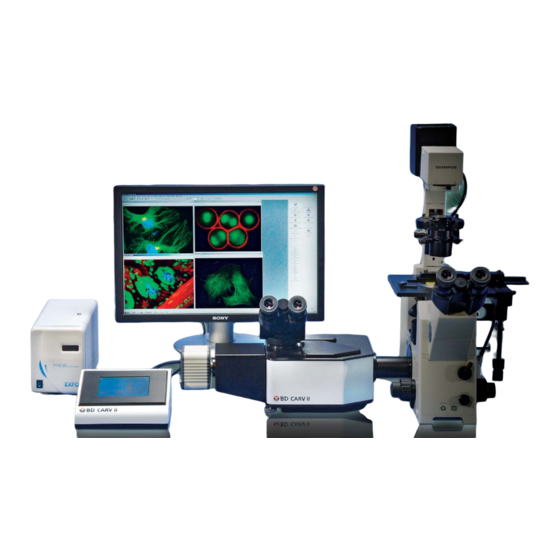
BD CARV II Specifications The following table details the specifications for the BD CARV II system. Table 1: BD CARV II Specifications Confocal Scanner Nipkow spinning disk (pinholes) Disk Scan Rate 1000 scans per second Pinhole Diameter µ Spectral Transmission 360 nm –... - Page 9 27.94(w) x 39.37 (L) x 15.24 cm Weight 14.5 lbs /6.6Kg Power 100-240 VAC, 1.2 A, 50/60 Hz Figure 1-1 Complete System Mounted on an Olympus IX 71 Microscope with a Hamamatsu Ocra ER Camera Chapter 1: BD CARV II Hardware...
-
Page 10: Bd Carv Ii Light Path
Arc Lamp: The light source is an EXFO X-Cite 120W Hg/metal halide lamp which delivers light to the CARV II via a 1.5 M EXFO liquid light guide. The liquid light guide delivery system produces even illumination and eliminates the need for arc lamp alignment. - Page 11 RS232 commands (software control). Camera: A wide range of high-end CCD cameras can be attached to the confocal unit to obtain confocal, wide-field, or dark-field images. Chapter 1: BD CARV II Hardware...
- Page 12 BD CARV II Installation and User’s Guide...
-
Page 13: Chapter 2: Bd Carv Ii Installation
BD CARV II Components • Filter Wheel Assembly Filter Descriptions Changing Filters and Dichroics • Binocular Assembly • Touch Pad Controller Assembly • Light Source (EXFO X-Cite 120) Assembly • CARV II Attachment to Microscope • Camera Attachment • Camera Focus Adjustment... -
Page 14: Bd Carv Ii Components
BD CARV II Components The following table lists all of the components of the BD CARV II: Part Picture Part Description Confocal head with two filter housing covers and camera tube attached. Eight-position excitation filter wheel with DAPI, GFP, and TEXAS RED exciter filters in position 1, 2 and 3. - Page 15 Part Picture Part Description Binocular attachment Two eyepieces x10 Camera tube shroud Touch pad CARV II power supply Chapter 2: BD CARV II Installation...
- Page 16 Part Picture Part Description Country-specific CARV II power supply AC cord Interconnect cable DB 9 RS232 cable BNC camera sync cable EXFO X-Cite 120 power supply BD CARV II Installation and User’s Guide...
- Page 17 Part Picture Part Description EFXO X-Cite 120 Hg/metal halide lamp 1.5M liquid light guide Country specific X-Cite 120 power supply AC cord 3mm T handle wrench Hex keys (1.5 mm & 0.05 mm) Chapter 2: BD CARV II Installation...
-
Page 18: Filter Wheel Assembly
Bubble level Filter Wheel Assembly CARV II accommodates three filter wheels: an eight-position excitation wheel, a five-position dichroic wheel, and an eight-position emission wheel. The user is provided with three single filter sets which come mounted on the filter wheels: DAPI, E-GFP, and Texas Red (see Filter Descriptions on page 19). -
Page 19: Filter Descriptions
Filter Descriptions Three filters are included in the CARV II system: • DAPI BrightLine™ FF409 Fluorescence • E-FFP BrightLine™ FF495 Fluorescence • Texas Red BrightLine™ FF593 Fluorescence ® NOTICE Graphs provided by Semrock ® DAPI BrightLine™ FF409 Fluorescence Optimized for these fluorophores:... - Page 20 GFP, Cy2™, CyQuant, DiO, EGFP, sgGFP™, wtGFP (non-UV excitation), YOYO-1, YO-PRO-1 Texas Red BrightLine™ FF593 Fluorescence ® Optimized for these fluorophores: Texas Red®, 5-ROX, Alexa Fluor 568 & 594, Calcium Crimson, Cy3.5™, HcRed, and MitoTracker Red BD CARV II Installation and User’s Guide...
-
Page 21: Changing The Filter Wheels
The filter wheels can be distinguished by the following features: • The emission filter wheel has eight, 25mm filter positions with symmetrical alignment holes. • The dichroic filter wheel is distinguished by the (25.7x36 mm) five-position dichroic mirrors. Chapter 2: BD CARV II Installation... - Page 22 • The excitation filter wheel has eight, 25mm filter positions with asymmetrical alignment holes. In order to access the filter wheels, remove the wheel housing covers which are held by magnets. BD CARV II Installation and User’s Guide...
- Page 23 The holes are designed so that the wheels will fit only one way. Take care not to touch the filters or mirrors when mounting the wheels. Once all three wheels are mounted, place the magnetically held covers back on the confocal head. Chapter 2: BD CARV II Installation...
-
Page 24: Changing Filters And Dichroics
Make sure that the arrow on both the excitation and emission filters is pointing towards the sample (towards the dichroic mirror) when placed in the filter wheels. BD CARV II Installation and User’s Guide... - Page 25 Using the hex key provided, unscrew the holding plates on either side of the dichroic position where you wish to replace or mount the mirror. Using a clean piece of tissue paper, gently remove the holding plates. Chapter 2: BD CARV II Installation...
- Page 26 If you hear a rattle you can tighten a bit more. Continue tightening the screw until the rattling stops. The filter wheels are now ready for mounting on the confocal head. BD CARV II Installation and User’s Guide...
-
Page 27: Binocular Assembly
The touch pad controller and the CARV II unit share a power supply. Attach the power supply to the touch pad. Attach one end of the interconnect cable to the touch pad controller and the other end to the CARV II unit. Attach one end of Chapter 2: BD CARV II Installation... -
Page 28: Light Source (Exfo X-Cite 120) Assembly
Attach one end of the liquid light guide to the lamp and insert the other end into the light guide entrance on the rear panel of the CARV II confocal head. Insert the light guide as far as it will go and then tighten it with the 0.05mm hex key. -
Page 29: Carv Ii Attachment To Microscope
Now tighten the holding screws firmly to the microscope. Camera Attachment A range of CCD cameras can be used with the CARV II. Mount the CCD to the C-mount at the end of the camera tube on the confocal head. Chapter 2: BD CARV II Installation... -
Page 30: Camera Focus Adjustment
For this step, it is not necessary to have a sample on the microscope. Using the CARV II control features within the imaging software do the following: Select the green florescent protein (GFP) filter set in the light path. - Page 31 This is necessary because, when the CARV II leaves the factory, it is focused using a CCD camera; however, the distance between the chip surface within the camera and the C-mount may vary from camera to camera.
- Page 32 Now that the pinholes are in focus, gently tighten the camera tube in place. Make sure that the camera image is squared to the screen by rotating the camera tube. Now tighten the camera tube firmly into position. BD CARV II Installation and User’s Guide...
-
Page 33: Chapter 3: Bd Carv Ii Touch Pad Controller
BD CARV II Touch Pad Controller The CARV II consists of two major components: the main unit and the touch pad controller. The main unit, which houses all of the optics and motors, must be mounted on a microscope. The touch pad controller, which contains virtually all the input/output for the CARV II, can be placed anywhere within reach of the interconnect cable. -
Page 34: Touch Pad Controller Connections
This power supply provides the necessary 5 and 12 V DC for the CARV II. To make sure the polarity and power capacity is correct, this supply should only be replaced with one of the same type. The power switch at the rear of the touch pad controller switches power for both the touch pad and the main unit simultaneously. -
Page 35: Touch Pad Controls
Touch Pad Controls The CARV II can be manually controlled with the touch pad. The touch pad will respond to firm pressure from blunt objects, such as a finger or pencil eraser. Do not actuate buttons on the touch pad with the writing tip of a pin or any other pointed, hard object. -
Page 36: Main Carv Ii Screen
Main CARV II Screen When the CARV II is powered on, the first screen displayed is the main screen. If, however, the touch pad is being pressed, the calibration screen is displayed. In this case, after the instructions on the screen have been followed, the main screen is displayed. - Page 37 FRAP Iris–Pressing this button displays the FRAP Iris screen. Refer to the FRAP Iris Screen on page 44 for more details. This button is not displayed when the confocal disk is in the light path. Chapter 3: BD CARV II Touch Pad Controller...
- Page 38 The prism graphic will change to the one below. BD CARV II Installation and User’s Guide...
-
Page 39: Secondary Carv Ii Screens
Presets–Pressing this button displays the Preset screen. Refer to the Presets Screen on page 46 for more details. Secondary CARV II Screens Pressing on the various icons in the CARV II main screen provides access to the following secondary screens: •... - Page 40 “+” and “-” button is added to the screen to adjust the calibration value, as in Figure 3-3. For more details on the calibration procedure, refer to Calibrating the Filter Wheels on page 49. BD CARV II Installation and User’s Guide...
-
Page 41: Dichroic Wheel Screen
Figure 3-3 Eight-Position Filter Wheel Screen with Calibration Function Activated Dichroic Wheel Screen When the dichroic wheel button on the Main Screen is pressed, Dichroic Wheel screen is displayed. Figure 3-4 Dichroic Wheel Screen Chapter 3: BD CARV II Touch Pad Controller... -
Page 42: Intensity Iris Screen
1050. If the confocal disk were in the light path, the text would change to read “Size With Confocal Disk In” and the setting would change accordingly. BD CARV II Installation and User’s Guide... - Page 43 Figure 3-6 Intensity Iris Screen The CARV II has two memory locations for the size of the variable intensity iris; one for when the confocal disk is in the light path, and one for when the disk is out. Each location is independently set and either one can be larger than the other or both can be equal.
-
Page 44: Frap Iris Screen
Screen allows manual control of the FRAP iris which creates a rectangular aperture on the image to enable controlled photo-bleaching of the sample. An example of the FRAP Iris Screen is shown in Figure 3-7. BD CARV II Installation and User’s Guide... - Page 45 Refer to Calibrating the Confocal Disk on page 48 for more details. Chapter 3: BD CARV II Touch Pad Controller...
-
Page 46: Presets Screen
Position 5, and the emission wheel doesn't move at all. The emission wheel remains in its last position because it is not involved with the FRAP exposure. Pressing the “Back” button displays the Main Screen. BD CARV II Installation and User’s Guide... -
Page 47: Calibration
Figure 3-9 Presets Screen Calibration Each CARV II instrument is individually calibrated at the factory before shipping. Each position of each device is aligned to the light path. Most of the factory calibration involves internal hardware that is not accessible in the finished instrument. -
Page 48: Calibrating The Confocal Disk
FRAP Iris Screen on page 44. The calibration buttons will be hidden if the BACK button is pressed and then BD CARV II Installation and User’s Guide... -
Page 49: Calibrating The Filter Wheels
CARV II, each position of each filter wheel has its calibration value stored in memory and each one can be adjusted independently. Every CARV II is loaded with the same default values designed to place each position in roughly the correct place. When each instrument is calibrated during production, these positions may be modified to optimize alignment. - Page 50 Refer to the software manual for the imaging software you are using for the syntax and a description of each command needed to do this. BD CARV II Installation and User’s Guide...
-
Page 51: Chapter 4: Bd Carv Ii Command Sets
BD CARV II Command Sets The following topics are covered in this chapter: • Software Communication • Devices • Command Conventions • Command Formats... -
Page 52: Software Communications
CARV II graphics in order to establish communication. The cable that joins the touch screen assembly and the main CARV II unit need not be present in order for the software to communicate with the touch screen–relevant commands will have a reaction on the touch screen display;... -
Page 53: Command Conventions
450 – 1050 Full Open When the CARV II is first turned on, all the devices are initialized to their “Home Position” listed in the chart above. The “H”(Home) command can also be used to return all the devices to these positions. - Page 54 The command buffer in the CARV II is 50 characters long. Compound commands must be 49 characters or less, including spaces and any requisite punctuation, to allow for the <CR> terminator. Overflowing the input buffer could result in either the loss of the beginning of the compound command as new commands overwrite the earlier commands or worse, completely errant behavior.
-
Page 55: Command Formats
– Lockout Touch Screen for Computer Control Format M<state><CR> Parameters <state> 0 = touch screen or computer controlled 1 = computer controlled only Return Value M<state><CR> Examples M0<CR> M0<CR> Touch screen now responds to touch and serial commands. Chapter 4: BD CARV II Command Sets... - Page 56 R0<CR> R1<CR> R1<CR> All commands generate a response to the host. NOTICE All lower case commands the “read” information from the CARV II will always respond regardless of the state set by this command. – “Rehome” All Devices Format H<CR>...
- Page 57 The shutter trigger source is now set as external. NOTICE External shutter triggering means that a 5VDC signal on the 50-ohm BNC connector on the main CARV II unit opens the shutter. 0VDC closes the shutter. Internal triggering comes from the touch screen, either manually or serially.
- Page 58 Device ID and position of Emission Filter Wheel <C> Device ID and position of Dichroic Filter Wheel <D> Device ID and position of Confocal Disk Slider <P> Device ID and position of Prism Slider BD CARV II Installation and User’s Guide...
- Page 59 Therefore, the “current” position is the last commanded position–not necessarily where the device actually is. Incorrect reporting is probably a sign of hardware malfunction. v – Read Version of Firmware Format v<CR> Parameters <version> Version of touch screen firmware Return Value v<version><CR> Chapter 4: BD CARV II Command Sets...
- Page 60 Examples v<CR> vVer. 1.02<CR> The touch screen firmware version is reported as Ver. 1.02. BD CARV II Installation and User’s Guide...
-
Page 61: Index
DB-9 connector 34 device touch pad controller assembly 27 IDs 52 positions 52 dichroic filter wheel 21 Dichroic Wheel Screen 41 wheel housing covers 22 DIN connector 34 Eight-position Filter Wheel Screens 39 BD CARV II Installation and User’s Guide...
Need help?
Do you have a question about the CARV II and is the answer not in the manual?
Questions and answers