Advertisement
Quick Links
Advertisement

Subscribe to Our Youtube Channel
Summary of Contents for Benzlers BD Series
- Page 1 Series BD - Screw Jacks Installation & Maintenance IMC-1.00GB01/11...
- Page 2 PRODUCT SAFETY IMPORTANT Product Safety Information General - The following information is important in ensuring safety. It must be brought to the attention of personnel involved in the selection of power transmission equipment, those responsible for the design of the machinery in which it is to be incorporated and those involved in its installation, use and maintenance.
- Page 3 1 IDENTIFICATION ................... 1 Machine description ..................1 1.1.1 Description of purpose ................1 1.1.2 Reasonably foreseeable misuse and prohibited usages ......1 1.1.3 System overview ..................2 1.1.4 Drawings/layouts ...................2 Manufacturer and technical data ..............3 1.2.1 Identification ...................3 1.2.2 External Electrical Power — Supply data ..........3 1.2.3 IP code, clear text ...................4 1.2.4 Environmental conditions and limits .............4 Product marking ....................5...
- Page 4 6 OPERATORS SETTINGS ETC ............... 27 Instructions from sub suppliers – Quick reference ........27 7 OPERATING INSTRUCTIONS ............... 27 Preparations before start ................27 7.1.1 Start-up of safety systems ..............27 Operation ......................28 7.2.1 Noise .....................28 7.2.2 General safety ..................28 7.2.3 Initial start up in a potentially explosive atmosphere ......28 7.2.4 Spillage of grease .................28 8 EMERGENCY, MISHAP AND SUSPENSION .........
- Page 5 ...in valid at ambient temperature +25° C NOTE: ABOUT GREASE! Benzlers screw jacks are filled with grease in EP-Ad- ditive quality at delivery. The lifting screw should be lubricated with the same type of grease. NOTE: ABOUT MANUALLY OPERATING THE JACK! AB Benzlers jacks are not primarily intended to be used manually using a crank, wheel or similar.
- Page 6 1.1.3 System overview 1. Trapezoidal lifting screw 2. Thrust and radial bearings 3. Grease with EP-additive 4. Housing of nodular cast iron 5. Alkyd paint 85 micron thickness in RAL 5009 6. Worm screw hardened and ground 7. Worm wheel of centrifugally cast tin bronze 8.
- Page 7 Classification of degree IK 08 The jack complies with IEC standards. The effect required depends on the load. For further information contact AB Benzlers. NOTE: ABOUT IK CODE! IK code means the classification of degrees of protec- tion provided by enclosure for motors against external mechanical impacts.
- Page 8 The lifetime of the jack are 200 operating hours (minimum). Where units are to operate in extreme conditions, or where they are to stand for long periods without running, e.g. during plant construction, consult AB Benzlers so that arrangements for adequate protection can be made.
- Page 9 1.3 PRODUCT MARKING 1.3.1 Product sign Product examples: Motor IEC motor flange Free input shaft Figur 2. Product sign – General description (type ”BD” as an example): 1. Line 1: Productcode 2. Line 2: – 3. Line 3: Exampel with – motor: Power (kW), Voltage (V) Frequency (Hz), Pos. of terminal box, Gap at delivery SHM –...
- Page 10 Figur 3. Extra sign according to ATEX directive NOTE: ABOUT ATEX! AB Benzlers must be consulted in advance to adapt the jack to comply with 94/9/EC (ATEX 100a). The jack will be marked with an extra sign according to ATEX directive. For more...
- Page 11 1.3.3 Understanding ATEX Directive - Markings CAUTION: RISK OF MACHINE DAMAGE! Only jacks ordered to comply with 94/9/EC (ATEX 100a) and marked with an ATEX sign are allowed to be used in an explosive environment. NOTE: ABOUT ANY OTHER EQUIPMENT FITTED TO THE SCREW JACK! Motors, gears, couplings, or any other equipment fitted to the screw jack unit must also comply with this directive.
- Page 12 For Category 2 and Category 3 see table below. Design of Design Application Zone of Use Safety Requirements High level of Safe with frequently Where explosive Zone 1 - An atmosphere where safety occu. Disturbances atmospheres are a mixture of air and flammable or with an likely to occur substances in the form of gas, vapor...
- Page 13 USE OF THIS MANUAL 2.1 GENERAL INFORMATION ABOUT THIS MANUAL The manual contains operating and safety instructions. Carefully study the manual and check that the manual is constantly available to the staff concerned. The instructions apply all types of work, the machine as well as immediate surroundings around the machine. Serious personal injuries and machine damages may occur if the information is not attended to.
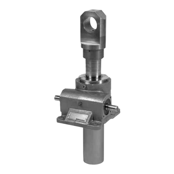
- Page 14 DESCRIPTION OF FUNCTION 3.1 OVERALL BD is a screw jack with single or double start trapezoidal lifting screw available with translating lifting screw. Figur 5. BD It is available in 8 sizes as standard. This type is the most frequently used screw jack, competively priced. NOTE: ABOUT STOP NUT! BD is available with a stop nut.
- Page 15 3.1.1 Control devices Control devices for the jack shall be designed according to the description below: • Control devices for setting power driven jacks in motion shall be of the hold-to-run type. • Control devices for power driven jacks shall be protected against unintentional operation. • The direction of movement caused by the control device shall be identified in a durable, unambiguous and easily recognisable manner. • The direction of motion can be identified by symbols or words. The identification can be attached to the control device itself or immediately alongside it. NOTE: ABOUT CONTROL DEVICES! Control devices are not included at standard delivery. WARNING: CRUSHING RISK! This protection prevents the possibility of pinched fingers or chruched hands, which can lead to permanent injury.
- Page 16 3.2 OPTIONS NOTE: IMPORTANT INFORMATION ABOUT ALL OPTIONS! For the up-to-date configuration of your Srew Jack, see the product code on the product sign that is mounted on the jack. 3.2.1 Stop nut (SM) Stop nuts can be fitted to all screw jacks, both above and below the main body. These must be included when there is an inherent risk of over travel resulting in the spindle becoming disengaged from the worm thread.
- Page 17 3.2.2 Stop nut (SM) + Limit Switch (LS) All jacks can be supplied with limit switches to suit most applications. Standard is two limit switches and one stop nut. Upper/lower limits can be mounted on the protection tube. Adjustable limits are also available on request.
- Page 18 3.2.4 LR - Locked Against Rotation (Tube) Protection tube manufactured in box section mild steel. Spindle end complete with nut (sized to suit box section). Figur 8. 1. Gear housing 2. Locking nut 3. Locking assembly (size dependent variant 1) 4.
- Page 19 3.2.6 Safety Nut (SHM) In certain applications the addition of a safety nut may be required. The object of the above is to prevent the load collapsing in the event of the lifting nut thread failing. NOTE: IMPORTANT INFORMATION ABOUT THIS OPTION! Load direction important! Combinations with other options are restricted.
- Page 20 3.2.7 Antibacklash (ABL) Where the loading on a screw jack can be in both tension and compression and the spindle backlash is critical, units can be supplied with a Back-lash Eliminator comprising of a modified worm wheel fitted with a secondary nut, allowing contact on both face and flank of driving thread.
- Page 21 AB Benzlers recommend that the integrator chooses the right category for emergency stops, and the correct security category of the emergency stop circuits. 4.1.2 Safety layout – emergency & safety stops zones AB Benzlers is not normally responsible for the installation. The integrator must draw a security layout of the whole system. 4.1.3 Hazard text...
- Page 22 4.2 OPERATORS LOCATIONS When the machine is started or in operation the operators shall not be in the danger zones. For more information see the risk analysis for the system. WARNING: CRUSHING RISK! It is not allowed to work under the raised load until it is secured by suitable means. It is necessary that the operator can watch the lifting device and the load during all movements.
- Page 23 4.2.3 Remaining risks Remaining risks from risk analysis, with no info elsewhere in this book, see also ”Personal protection, unintentional use” on page 20. WARNING: RESIDUAL RISKS! Integrators must be aware of the residual risks when drawing the security layout. Ensure that no operators can be situated in the danger zones during operation. DANGER: RISK OF BURNS! Be aware of hot surfaces during operation. DANGER: RISK OF ENTANGLEMENT! Be aware of moving parts.
- Page 24 4.3 PERSONAL PROTECTION, UNINTENTIONAL USE Local rules for personal protective equipment apply; however, take special care that • your clothes fit with no loose ends improperly fastened. • no other objects are hanging loose outside your clothing. NOTE: IF REQUIRED, WEAR PROTECTIVE CLOTHING! Wear protective clothing during service and mainte- nance. NOTE: IF REQUIRED, WEAR PROTECTIVE GLOVES! Wear protective gloves during service and maintenance.
- Page 25 In the event that equipment is to be held in storage, for a period exceeding 6 months, prior to installation or commissioning, AB Benzlers must be consulted regarding special preservation requirements. Unless otherwise agreed, equipment must be stored in a buil- ding protected from extremes of temperature and hu- midity to prevent deterioration.
- Page 26 5.3 PREPARATORY WORK BEFORE INSTALLATION AND ASSEMBLING 5.3.1 Prior to Installation CAUTION: RISK OF SKIN IRRITATION! External gearbox components may be supplied with preservative materials applied, in the form of a waxed tape overwrap or wax film preservative. Gloves should be worn when removing these materials.
- Page 27 5.3.3 Lifting The easiest way to lift the screw jack is with a lifting strap attached to the bushings on each side as near the housing as possible. In the case of a long lifting screw the screw jack can be lifted with straps attached to the bushing on the lifting screw side and to the protection tube (to ensure balance).
- Page 28 5.4 INSTALLATION 5.4.1 Fitting the screw jack to the machine • Check that the threaded spindle is square to the mounting plan and that the load and threaded spindle are on the same axis to ensure that the jack is installed in a manner that does not create radial loads. • Check that connecting shafts and worm shafts are exactly aligned. • When jacks, shafts, gear boxes, etc. have been connected, it should be possible to turn the main driving shaft by hand (provided that the jacks are unloaded). If there are no signs of seizure or misalignment, the jack system is now ready for normal operation.
- Page 29 5.4.2 Units for use in a potentially explosive atmosphere Object Checklist Atmosphere Check the nameplate of unit corresponds with the sites potentially explosive atmosphere classification. Temperature Check that ambient temperature falls within lubricant gra- de recommendations. Installation Check that no potentially explosive atmosphere exists during installation. Ventilation Make sure that screw jack unit is sufficiently ventilated with no external heat input –...
- Page 30 CAUTION: RISK OF MACHINE DAMAGE! The motor used for the jack must comply with the jack according to AB Benzlers’ recommendations and the standard EN 60204-32. A motor which is too strong can lead to a...
- Page 31 OPERATORS SETTINGS ETC. Prior to settings etc, make sure that you have read and understood the section ”Safety information” on page 17 and forward. 6.1 INSTRUCTIONS FROM SUB SUPPLIERS – QUICK REFERENCE See motor manual for more information (if motor is included in the order the motor manual shall be provided at delivery). OPERATING INSTRUCTIONS Prior to operation, make sure that you have read and understood the section ”Safety information” on page 17 and forward. DANGER: CRUSHING RISK! Never start the machine when people are inside the risk area, inside the mechanical protection of the machine, or up on the machine.
- Page 32 EMERGENCY, MISHAP AND SUSPENSION 8.1 CHANGE OF DIRECTION OF MOTION, RELIEF OF STORED ENERGY AB Benzlers recommend that the controll system for the jack is built in a way that makes it easy to change the direction of movement in case of emergency.
- Page 33 In the event that equipment is to be held in storage, for a period exceeding 6 months, prior to installation or commissioning, AB Benzlers must be consulted regarding special preservation requirements. Unless otherwise agreed, equipment must be stored in a dry environment protected from extremes of temperature, dust, dirt and humidity to prevent deterioration.
- Page 34 9.1.1 Prior to any maintenance operations • De-energise the drive and secure against unintentional switch on. • Wait until the unit has cooled down – danger of skin burns & pressure build up. NOTE: ABOUT CHANGES! Changes which do not comply with SS-EN 1494+A1:2008 are not allowed. WARNING: RISK OF BURNS! During operation, gear units may become sufficiently hot to cause skin burns. Care must be taken to avoid accidental contact.
- Page 35 9.4 MAINTENANCE AND CLEANING BY USERS 9.4.1 Lubrication – general • All worm gear screw jack units are despatched with grease in the worm wheel stage. AB Benzlers grade and type of grease will be stamped on the sign. • Lubricating the threaded spindle is the responsibility of the customer and must be done using lubricants according to the table ”Typ of grease (* = standard at delivery)” on page 31. • Lubricating the threaded spindle is an important and determining factor in the proper functioning of the jack. • It must be done in intervals that assure a constant coat of clean lubricant between the contact parts. • Insufficient or improper lubrication leads to increased heat and wear, which naturally reduces the operating life and promotes breakdown. WARNING: RISK OF SKIN IRRITATION! Prolonged contact with lubricants can be detrimental to the skin.
- Page 36 9.4.3 Screw jack body grease quantity Type Grease quantity (if empty) BD/BDL/BDKL 27 0.3 kg BD/BDL/BDKL 40 0.5 kg BD/BDL/BDKL 58 0.9 kg BD/BDL/BDKL 66 1.2 kg BD/BDL 86 1.4 kg BD/BDL 100 2.5 kg BD/BDL 125W 5.2 kg BD/BDL 200 15 kg BDK 27 0.4 kg...
- Page 37 9.4.4 Lubrication – periods • Periodic inspection. – The spindle thread shall always be kept well covered with grease and are to be relubricated at regular intervals. – The service life of the unit depends largely upon regular and effi- cient lubrication. –...
- Page 38 NOTE: THE WEAR MUST BE CHECKED REGULARLY! For monitoring of change of worm wheel wear in thread - the same procedure must be applied to get compara- ble values! If necessary, contact Benzlers service department. NOTE: ABOUT WEAR DISTANCE! The values at delivery can differ between individuals (dimension = 25 - 37% of thread pitch).
- Page 39 9.4.7 Measuring of thread wear in running nut 9.4.8 Antibacklash Where the loading on the screw jack can be in both tension and compression and the spindle backlash is critical, units can be supplied with a “Back-lash Eliminator” comprising of a modified worm wheel fitted with a secondary nut, allowing contact on both face and flank of drivning thread. During operation excessive backlash can be removed by adjustment of the top cover.
- Page 40 9.5.1 Renew grease Renew grease every 400 hours of duty or after 24 months operation at the latest. See picture and table below to disassemble and assemble the jack. Item Housing Cover Bushing Worm screw Worm wheel Bearing Support ring Bearing Ring Ring...
- Page 41 If still • from motor flange b) Defective gasket. grease leaks contact AB Benzlers. • from gear unit flange b) Contact AB Benzlers. • from output end oil seal 1) It is normal for small amounts of oil / grease to leak out of the oil seal during the running in period (24 hours running time).
- Page 42 10.1.2 Other errors Errors of alignment fall into categories of angularity and eccentricity, or a combination of both. NOTE: ABOUT SHAFT ALIGNMENT! Errors of angularity should be checked for, and corrected, before errors of eccentricity. Alignment in accordance with the following procedure will ensure vibration levels meeting those set out in ISO 10816 Part 1.
- Page 43 The permitted angularity error is as follows: Type of Coupling Allowable Gap (G) (mm) Rigid Coupling G = 0.0005 D All other types Please see appropriate Installation and Maintenance Manual for coupling type fitted. NOTE: ABOUT ‘D’! D is the diameter (mm) at which the gap is measured. Errors of Eccentricity: Figur 19.
- Page 44 In case of claims on spare parts etc., pack together and mark with the order- or project number. 11.4 LIST OF SPARE PARTS AND CONSUMABLES 11.4.1 Drawings and spare part lists For drawings and spare part lists contact AB Benzlers or go to www.benzlers.com. 11.4.2 Consumables For recommended lubrications see ”Lubrication – temperature limitations” on page 31.
- Page 45 CONTACT US AUSTRALIA DENMARK SWEDEN & NORWAY UNITED KINGDOM Radicon Transmission Benzler Transmission A/S AB Benzlers Radicon Transmission UK Ltd (Australia) PTY Ltd Fuglebævej 3D Box 922 (Landskronavägen 1) Unit J3 Australia DK-2770 Kastrup, 251 09 Helsingborg Lowfields Business Park,...
- Page 46 Benzlers Denmark +45 36 34 03 00 Finland +358 9 340 1716 Germany +49 800-350 4000 Sweden +46 42 186800 The Netherlands +31 77 324 59 00 www.benzlers.com Radicon Thailand +66 3845 9044 United Kingdom +44 (0) 1484 465 800 USA +1 847 593 9910 www.radicon.com...
Need help?
Do you have a question about the BD Series and is the answer not in the manual?
Questions and answers