Samsung SyncMaster VC240 User Manual
Video conference system
Hide thumbs
Also See for SyncMaster VC240:
- User manual (62 pages) ,
- Reference manual (39 pages) ,
- Quick start manual (17 pages)

Related Manuals for Samsung SyncMaster VC240


Summary of Contents for Samsung SyncMaster VC240
-
Page 1: User Guide
SyncMaster VC240 Video Conference System User Guide Information in this user guide is subject to change without prior notice for performance improvement. ◀ ▶... - Page 2 © 2010–2011 Samsung Electronics Co., Ltd. All rights reserved by Samsung Electronics Co., Ltd. You are prohibited from unauthorized use or reproduction of any of the information in this user guide without prior approval from Samsung Electronics Co., Ltd.
-
Page 3: Table Of Contents
Contents 1 Introduction 1.1 Features ....... 1.2 Package Contents ......Accessories . - Page 4 4.6 Zooming a Remote Caller’s camera ....4.7 Remote Presentation ......5 Video Conferencing with RADVISION SCOPIA Systems 6 Custom Settings 6.1 Menu Language...
-
Page 5: Introduction
Introduction 1.1 Features The video conference system VC240 can be used for various purposes: • Use VC240 as an ordinary monitor. • Make video calls over the Internet or a local network to VC240 or other types of video conference systems. •... -
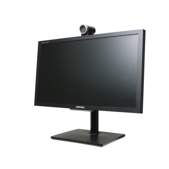
Page 6: Basic View
Basic View Camera Microphone Remote control sensor Speaker This camera cannot be connected directly to a computer and thus cannot be used for purposes other than video calls. • is used to open or close a menu, return to the last menu, or delete the last character you typed. -
Page 7: Remote Control
1.3 Remote Control You can control the monitor by using the buttons on the remote control or on the bottom of the monitor. Be sure the remote control is not lost. powers on or off the monitor. See §2.8. changes the video mode. See §2.5. splits the screen to display the pictures from the camera and from the PC at the same time. -
Page 8: Setup
fire may result. • Do not use an unauthorized power cord. The power cord should have been supplied by Samsung. Otherwise, an electric shock or fire may result. • Place the power plug in an easily accessible area so that you can unplug the power cord in order to completely cut the power to the product when there is a problem. -
Page 9: Cleaning
High voltage runs through the product. Do not attempt to disassemble, repair, or modify the product on your own. Otherwise, an electric shock or fire may result. Contact Samsung’s service center for repair. • If the product generates a strange noise, a burning smell, or smoke, re- move the power cord immediately, and contact Samsung’s service cen-... - Page 10 flammable object (paper, match, etc.) into the vent or ports of the prod- uct. If water or any foreign substance enters the product, be sure to power off the product, remove the power cord, and contact Samsung’s service center. Otherwise, product failure, a fire, or an electric shock may result.
-
Page 11: Assembling The Product
• Do not set the volume really high when you use headphones. A really high volume may cause your hearing to weaken. • Be sure the batteries are oriented in the right direction. Otherwise, a fire, personal injury, or contamination may result from an explosion or internal fluid leakage of the batteries. -
Page 12: Theft Prevention
Tightly fasten the screw on the bot- tom of the base to the stand. Be sure you do not remove the fix- ing pin from the stand before you connect the stand to the base. Oth- erwise, injury may result. connecting the stand to the base, remove the fixing pin, and adjust the height of the stand. -
Page 13: Mounting The Monitor To A Wall
Attach the wall-mount bracket, and fasten the screws. Samsung is not liable for any defect caused by using a wall-mount bracket that does not comply with the VESA standards. Blocking Electromagnetic Waves The ferrite core can be used to block electromagnetic waves. Thread the LAN cable through the ferrite core and tie a knot with the core close to the LAN port. -
Page 14: Connections
2.3 Connections Connecting to a PC The monitor has two video inputs for connecting to a PC. One is for DVI, and the other is for VGA. Using a dig- ital signal, DVI offer clearer pictures than VGA which uses an analog signal. Thus, it is best to connect the monitor to a PC via DVI rather than VGA. -
Page 15: Connections For Video Calls
Connections for Video Calls To make a video call, the monitor should be connected to a network. Connect the LAN cable from the LAN port on the router to the LAN port on the monitor. If the router has no more ports available for the monitor, connect one port on the monitor to the router and then the other port on the monitor... -
Page 16: Powering On The Monitor
2.5 Powering On the Monitor Before you power on the monitor, insert the bat- teries into the remote control, observing the po- larity, which is marked on the base of the battery compartment. If the monitor does not respond to the remote control, the batteries have been discharged. -
Page 17: Navigating Between Menus
Table 3: Video signal mode Resolution Horizontal Vertical Clock frequency frequency frequency (kHz) (Hz) (MHz) IBM, 640 ☓ 350 31.469 70.086 25.175 IBM, 720 ☓ 400 31.469 70.087 28.322 MAC, 640 ☓ 480 35.000 66.667 30.240 MAC, 832 ☓ 624 49.726 74.551 57.284... -
Page 18: Keyboard Modes
2.7 Keyboard Modes You can type in uppercase letters, lowercase letters, numbers, and several symbols using three types of keyboard modes. The current keyboard mode is shown in the right side of the field: ABC indicates uppercase mode, abc lowercase mode, and 123 number mode. To change the keyboard mode, press repeatedly until the keyboard mode you want is displayed. -
Page 19: Power-Saving Modes
2.8 Power-saving Modes As shown in Table 4, there are three types of power supply modes. The moni- tor enters active mode after you have pressed Table 4: Power specification Input power 100–240 V Active mode Less than 85 W Standby mode Less than 35 W Max. - Page 20 Press to open the Setup screen. Select an interval for activating Standby mode. Each interval is a mul- tiple of 10 minutes from 10 to 60 minutes. If Standby is set to 10 minutes, the monitor will automatically turn off and switch to standby mode after the remote control has been left idle for 10 minutes.
-
Page 21: Network And Call Settings
Network and Call Settings 3.1 Network Settings Consult your network administrator, and configure the network settings for the monitor. The IP address can be assigned in one of the following two ways. Static IP address: The same IP address will always be assigned to the moni- tor whenever it is powered on. - Page 22 whereas the invalid items will be indicated by a Assign the monitor a name so that it can be identified by other devices connected to the network. Select Display Name, and enter a name. The data transmission rate and mode are determined while the monitor tries to connect to a router.
-
Page 23: Data Transmission Mode
3.2 Data Transmission Mode You can make or receive calls using one of the following data transmission protocols: • H.323 • Session Initiation Protocol H.323 Data Transmission To make calls using the H.323 telephone number mode (E.164), configure the settings as follows: to open the Setup screen, and select Network. -
Page 24: Nat Traversal
Press to open the Setup screen, and go to Network. Select User Name and enter a name. In SIP you can use both name and number in URI for dialing. Set Network Preference to SIP. Select SIP Settings. a) Set SIP Proxy Server to On. b) Fill the Display Name, Server Address, and Password fields. -
Page 25: Call Settings
Set NAT Traversal to Yes. Use NAT Auto Discovery on for system to discover it’s external public IP automatically. Following OK, discovered external public IP will be displayed. Use NAT Auto Discovery off for manual enter public IP address. When NAT Traversal is set to Yes then Gatekeeper and H.460 Traversal must be set to Off and vise versa. - Page 26 resolution, max frame rate will be used. A higher sharpness will compromise simultaneity. For instance, a pic- ture of you waving a hand will appear delayed for a remote caller. For simultaneity, set Video Mode to Motion. A bad network connection sometimes corrupts the picture, which ap- pears as a mosaic, during a call.
-
Page 27: Time
Time Set the clock precisely so your video calls will be logged accurately. Press to open the Setup screen, and select Clock. The time server will allow the clock to always have the precise time. To use the time server, set Clock Mode to On. Select the Time Zone corresponding to your region. - Page 28 or time using the number keys on the remote. In Date Format, DD indicates the day, MM the month, and YYYY the year. If Date Format is set to DD/MM/YYYY and a call was made on July 18, 2010, the date will be displayed as 18/07/2010. If Time Format is set to 12 Hours and a call was made at 6:24 p.m., the time will be displayed as PM 06:24.
-
Page 29: Camera
Camera Your picture may appear too dark or bright, or different in color for your remote caller, depending on your ambient light intensity. Change several settings so the remote caller can see you clearly: Press to open the Setup screen, and go to Camera. Select the correct frequency from Power Frequency. - Page 30 Rotating your monitor to a vertical orientation will rotate the camera, and thus your image will appear rotated on the remote caller’s screen. To resolve this, the remote caller should also rotate his monitor to a vertical orientation, and you and the remote caller should set Flip to Horiz.
-
Page 31: Video Call
Video Call 4.1 Making a Call You can make a call, following the steps below: Press The screen will display the recent-call log on the left, the phone number field in the middle, and your image on the right. If you want to hide your image or make a call to someone without a camera, set Call Type to Voice. -
Page 32: Answering A Call
To end the call, press Select Yes. The call will be disconnected. To view the recent-call log, select Call History. Refer to about the recent-call log. . 10 To open the phone book, select Phone Book. Refer to 4.2 Answering a Call Configure the call answering settings, following the steps below: §4.5 for details... -
Page 33: Screen Layout
When On + Mic Mute is selected, an incoming call will automatically be connected, but your voice will not be heard by the remote caller. If you want to refuse all incoming calls, set Do not Disturb to On. An incoming call will be indicated by a ringtone. If you want to mute the ringtone, select Audio, and set Sounds to Off. - Page 34 Select a size from PIP Size. Two sizes are available. Select a location from PIP Position. Five locations are available: bottom right, top right, top center, top left, and bottom left. The area on the screen concealed by the smaller picture will not be shown.
-
Page 35: Making A Phone Book
4.4 Making a Phone Book You can make calls easily by using the phone book. To open the phone book, press Adding a Group It is best to create a group before adding a phone number so you can search and manage numbers easily. -
Page 36: Deleting A Group
Deleting a Group Select a group and press Select Delete. The selected group will be deleted, and its contacts will be moved to the Unassigned group. Adding a Contact Go to All and select Add Contact. Enter a contact name in the Name field, and fill at least one of the IP, URI, and Phone Number fields. -
Page 37: Editing A Contact
Editing a Contact Select a contact and press To view details of the contact before editing, select View. Select Edit and change the information. Select OK to save the changes and exit. Deleting a Contact Select a contact and press ◀... - Page 38 Select Delete. Select OK. The contact will be deleted. To delete all contacts, select Delete All. Select OK. All the contacts will be deleted. To delete more than one contact at the same time, select the contacts and press . The selected contacts will be indicated by a After selecting all the contacts you want to delete, press last selected contact highlighted, and select Delete.
-
Page 39: Making A Call
Making a Call Select a contact and press Alternatively, press and select Call. Searching a Contact You can search a contact using the contact name or IP address. Press to open the phone book. Move the cursor to the input field. Enter capital or lowercase letters to search for contacts with names con- taining the same letters. -
Page 40: Recent-Call Log
4.5 Recent-Call Log To view the recent-call log, press and select Call History. Alternatively, press and select Call History. • To view the incoming-call log, select Received. • To view the outgoing-call log, select Sent. To view the missed-call log, select Missed. •... -
Page 41: Deleting A Call From The Call Log
Deleting a Call from the Call Log Select a call from the call log, and press Select Delete. Select OK. The call will be deleted. To delete all the calls from the call log, select Delete All. Select OK. All the calls in the call log will be deleted. To delete more than one call from the call log at the same time, select the calls and press After selecting all the calls you want to delete, press... -
Page 42: Making A Call
selected call highlighted, and select Delete. Select OK. The selected calls will be deleted from the call log. Making a Call Select a call from the call log, and press Alternatively, press and select Call. ◀ ▶ 4.5 Recent-Call Log... -
Page 43: Adding A Contact To The Phone Book
Adding a Contact to the Phone Book You can add a contact from the call log to the phone book. Select a call from the call log and press Select Save. Select OK to save the new contact and exit. 4.6 Zooming a Remote Caller’s camera You can zoom in or out the remote caller’s camera if it has the zooming func- tion. -
Page 44: Remote Presentation
4.7 Remote Presentation You can send the picture from your computer to the remote caller and give a remote presentation during a call: Press to open the Setup screen, and go to Call Control. Set Pre- sentation Source to DVI if the monitor is connected to the PC via DVI. Otherwise, select PC. -
Page 45: Video Conferencing With Radvision Scopia Systems
Video Conferencing with RADVISION SCOPIA Systems You can use VC240 by itself for a high-definition video call between two people (point-to-point video call). Enjoy additional features such as central- ized management, multi-party conferencing, recording and streaming, and firewall traversal by adding a video conferencing system with RADVISION SCOPIA. - Page 46 lows users to take conferencing wherever they go. SCOPIA Desktop is de- signed to meet the demands of high-performance video conferencing with a standard PC and Internet connection. The latest in video technology are included, providing HD H.264 format for viewing both participants and for data collaboration.
- Page 47 USA/AMERICAS EMEA T. +1 201 689 6300 T. +44 20 3178 8685 F. +1 201 689 6301 F. +44 20 3178 5717 infoUSA@radvision.com infoUK@radvision.com APAC T. +852 3472 4388 F. +852 2801 4071 infoUK@radvision.com ◀ ▶...
-
Page 48: Custom Settings
Custom Settings Some menu options are disabled depending on the video mode, as shown below. VC mode ☓ General Max. Power Saving ◯ Standby ◯ Picture Video Mode ◯ Color ◯ Tint (G/R) ☓ MagicBright ☓ Auto Adjustment ☓ Screen ☓... -
Page 49: Picture
6.2 Picture PC or DVI Mode Adjusting the Brightness You can adjust the brightness, following the steps below. Press to open the Setup screen, and go to Picture. Select an option from MagicBright. If the option you want is not available, select Custom, and then adjust Contrast, Brightness and Sharpness. - Page 50 Then select Reset Picture Mode. Adjusting the Color Tone You can change the color tone: Press to open the Setup screen, and go to Picture. Select Picture Options. ◀ ▶ 6.2 Picture...
- Page 51 Select an option from Color Tone. If the option you want is not available, select Custom, and then adjust R-Gain, G-Gain, and B-Gain, which indicate red, blue, and green re- spectively. To change the color tone of the picture to yellow, change R-Gain and G-Gain to 100 and B-Gain to 0.
- Page 52 Decrease or increase Coarse to narrow or widen the picture respec- tively. To finely adjust the picture width, select Fine. If the picture is not centered on the screen, select PC Position and then adjust the picture location using the To reset the picture size and location, select Image Reset.
-
Page 53: Vc Mode
for movies. VC Mode Adjusting the Brightness and Color Intensity You can change the brightness and color intensity: Press to open the Setup screen, and go to Picture. Select an option from Mode. Adjust Contrast, Brightness, Sharpness, Color, and Tint (G/R) for the ◀... - Page 54 selected option. To reset the custom settings for the current Mode, select Picture Reset. Then select Reset Picture Mode. ◀ ▶ 6.2 Picture...
- Page 55 Adjusting the Color Tone You can change the color tone: Press to open the Setup screen, and go to Picture. Select Picture Options. Set Color Tone to Cool1, Cool2, Normal, Warm1, or Warm2. Noise can occur in the picture of a very dynamic video. To avoid noise, set Digital NR to Off, Low, Medium, High, or Auto.
-
Page 56: Security
6.3 Security You can set the monitor to be accessed only via a password. Press to open the Setup screen. Select Security. Selecting Security will always display the following password prompt. Enter the current password. The initial password is 0000. This is working only from 1004.17. Set Functions Lock to On. -
Page 57: Reset Settings
6.4 Reset Settings You can return the monitor to its default settings: Press to open the Setup screen. Select Reset Settings. The monitor will restart itself after resetting. Note that all user con- figurations and the call logs will also be deleted. 6.5 Software Update You can update the monitor software over the network. - Page 58 Select SW Upgrade to start an update. Enter the IP address of the software-update server in the input field, and press . Contact our service center or Radvision for getting the up- dated released SW version. Upgrade server should be installed locally. A software will appear on the server after setup.
-
Page 59: Troubleshooting Guide
(POWER S/W) on the back of the monitor is turned on. Service Center Contact our service center for more information. (Please check the model name and serial number in advance.) NORTH AMERICA CANADA 800-SAMSUNG (726-7864) MEXICO 800-SAMSUNG (726-7864) 800-SAMSUNG (726-7864) FRANCE 01 48 63 00 00 GERMANY... -
Page 60: Index
Index Call Type, Camera, Change PIN, Check signal cable, Clock, 4:3, Clock Mode, 12 Hours, Clock Set, 16:9, Coarse, 18/07/2010, Color, 44, 18:24, Color Tone, 47, 24 Hours, Connected to, 123, Contrast, 45, Cool1, Cool2, ABC, Custom, 45, abc, Accept, Add Contact, Date Format, Add Group,... - Page 61 Received, Unassigned, Reject, URI, Rename, User Name, Reset Picture Mode, 46, Reset Settings, 52, VESA, R-Gain, 44, Video Mode, 22, RGB IN, View, 33, Voice, Save, Screen, 44, Warm1, Security, Warm2, Sent, White Balance, Server Address, Setup, Sharpness, 45, YYYY, SIP, SIP Proxy Server, SIP Settings,...