Table of Contents
Advertisement
Quick Links
Advertisement
Table of Contents

Related Manuals for Sena Parani-SD1000U


Summary of Contents for Sena Parani-SD1000U
- Page 1 Parani-SD1000U User Guide Version 1.0.0 2010-10-22...
- Page 2 This device is not approved for life-support or medical systems. Changes or modifications to this device not explicitly approved by Sena Technologies will void the user's authority to operate this device.
-
Page 3: Fcc Information To User
To reduce potential radio interference to other users, the antenna type and its gain should be so chosen that the equivalent isotropically radiated power (EIRP) is not more than that required for successful communication. Technical Support Sena Technologies, Inc. 210 Yangjae-dong, Seocho-gu Seoul 137-130, Korea Tel: (+82-2) 573-5422 Fax: (+82-2) 573-7710 E-Mail: support@sena.com... -
Page 4: Revision History
Revision History Revision Date Name Description V1.0.0 2010-10-22 JH Park Initial Writing... - Page 5 Contents 1. Introduction 1.1. Overview ............................8 1.2. Product Specification........................9 2. Getting Started USB Driver Installation ........................10 2.1..............................10 2.2. Operation Modes........................11 2.3. LED Indicators.......................... 11 2.4. Serial Ports..........................12 2.5. Data Bit.............................12 2.6. Hardware Flow Control ......................12 2.7. Reset to Factory Defaults......................13 2.8.
- Page 6 A.3.7. AT+BTINQ? .........................29 A.3.8. AT+BTLAST?.......................29 A.3.9. AT+BTVER? ........................29 A.3.10. AT+MLIST?........................29 A.3.11. AT+BTMODE,n ......................29 A.3.12. AT+MULTI,n .......................29 A.3.13. +++ ..........................29 A.3.14. AT+SETESC,nn ......................29 A.3.15. ATO (ATOx, ATObdaddr) ...................29 A.3.16. AT+BTCANCEL ......................29 A.3.17. AT+BTSCAN......................29 A.3.18. AT+BTSCAN,n,to.......................29 A.3.19. AT+BTSCAN112233445566,to ..................29 A.3.20. ATD ..........................29 A.3.21.
-
Page 7: Appendix D: Warranty
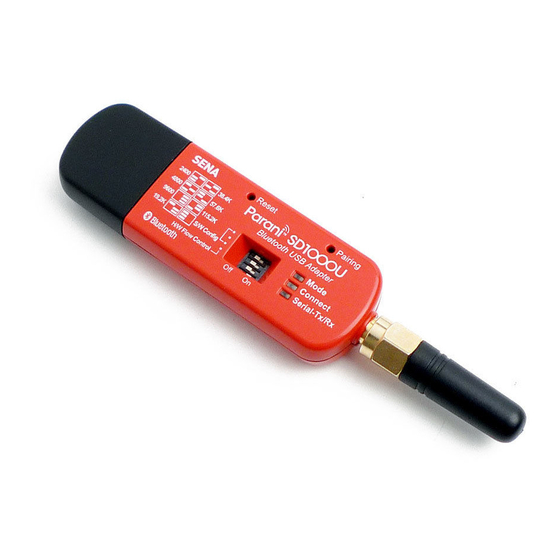
B.28. S56: BD Address of Last Connected Device .................29 B.29. S57: Slave Disconnect Timeout (default 3) ................29 B.30. S58: MAX TX POWER (default 0) ..................29 B.31. S59: Current Slave in Communication (default 0) ..............29 B.32. S60: Reconnect Time Interval (default 5) ................29 B.33. - Page 8 1. Introduction 1.1. Overview Parani-SD1000U is a terminal device for wireless serial communication using Bluetooth 2.0+EDR technology that is an international standard of short range wireless communications. Parani-SD1000U can communicate with other Bluetooth devices; user may connect other Bluetooth devices that support the Serial Port Profile.
-
Page 9: Product Specification
1.2. Product Specification Parani-SD1000U Bluetooth Interface Bluetooth v2.0 + EDR Class 1 Working distance: Dipole Dipole 150 meters Antenna Antenna Dipole Dipole 200 meters Antenna Antenna Dipole Dipole 300 meters Antenna Antenna Configuration ParaniWIN, Modem AT command set ParaniUpdater Firmware Update... -
Page 10: Getting Started
2. Getting Started 2.1. USB Driver Installation In case the USB interface is used for the communication between the development board and the computer, the corresponding software driver needs to be installed on the computer. Windows XP and later versions already include the USB driver. When Windows asks for the location of the USB driver, you can select the option to “install the software automatically”... -
Page 11: Operation Modes
2.2. Operation Modes In addition to the serial port configurations the SD1000U also requires some settings for Bluetooth. For getting the most out of SD1000U, user should understand the following Bluetooth connection schemes. A Bluetooth device can play a role as a master or slave. Master tries to connect itself to other Bluetooth devices, and slave is waiting to be connected from other Bluetooth devices. -
Page 12: Serial Ports
Table 2-2 The SD1000U LED Indicators Indicator Mode LED Connect LED Mode 0 Green ┏━━━━━ Mode 1 Green (every 1 sec) ┏┓ Mode 2 Green (every 3 sec) ┏┰┓ Mode 3 Green (every 3 sec) ┏┰┰┓ Connected Green (every 1 sec) ┏┓ 2.4. -
Page 13: Reset To Factory Defaults
When hardware flow control is not being used, the SD1000U clears the buffer to secure room for the next data when the buffer becomes full. This can mean a loss of data may occur. As the transmission data becomes large, the possibility of data loss becomes greater. For large data transmissions, the use of hardware flow control is highly recommended. -
Page 14: Pairing Button
2.9. Pairing Button SD1000U provides Pairing Button for instant configuration without a PC to make an automatic connection between two SD1000Us. In this example we will refer to the two SD1000Us as SD1 and SD2. (Only single connection mode) Step 1. Turn on SD1 and SD2 and reset both of them by pressing Factory Reset Button. Step 2. - Page 15 4. Connected Master every second 2.10. Software and Utility This configuration software and utility for firmware update is included with the product, which also can be downloaded from http://www.sena.com Table 2-8 Configuration Software Software Purpose Operating System ParaniWIN Configuration...
- Page 16 Figure 2-3 Main Window Figure 2-4 Information Window Serial port settings can be changed by <Start Configuration> and <ParaniWIN Configuration> of ParaniWIN in the menu bar at upper left corner of the window without re-running the ParaniWIN program.
- Page 17 Figure 2-5 Menu Bar at Upper Left corner of ParaniWIN When the ParaniWin software is able to access the SD1000U properly, the icons in the left side window come will become available for use. In device configuration window, hardware reset can be executed or operation mode and RS232 can be configured as well.
- Page 18 SD1000U has 4 response messages, ‘OK’, ‘ERROR’, ‘CONNECT’, and ‘DISCONNECT’. In some cases, these responses can affect the host system unexpectedly. To prevent this, user can set the Command response to ON or OFF. For SD1000U, hardware flow control can be configured only by dip switch. And parity, stop bit can be configured only SW config mode.
- Page 19 Figure 2-8 Signal Strength Test The signal strength test shows LInkQuality and RSSI values. The closer LinkQuality is to 255 and RSSI is to 0, this means the SD1000U has a good connection to the connected Bluetooth device. In general, the wireless connectivity is at its best within 10 meters. You can push the STOP button at anytime in order to terminate the signal strength test.
- Page 20 Figure 2-9 Connection (in) Window If the Connection Wizard icon is clicked, an easy to use pairing menu will appear: Figure 2-10 Connection Wizard Window In this example we will refer to the two SD1000Us as SD1 and SD2 respectively. To use this menu, please do the following:...
- Page 21 Step 1. Connect SD1 and then push the START button. Step 2. Disconnect SD1, connect SD2 and then push the Next button after setting up Slave configuration. At this time, the dip switch value should be ATcmd mode. The flow control setting can be changed only through dip switch.
- Page 22 2.13. ParaniUpdater SD1000U supports firmware updates. You can download new firmware images for the SD1000U at http://www.sena.com. With the ParaniUpdater, you can update the firmware of SD1000U by selecting the firmware image file and pushing Start button. * Note: DO NOT power off SD1000U while the firmware update is progressing, this may damage the...
-
Page 23: Terminal Program
Figure 2-13 ParaniUpdater Window 2.14. Terminal Program A terminal program is typically an application that will enable a PC to communicate directly with a modem. If you are using Windows 98SE or higher version of Windows, HyperTerminal program is included as part of the operating system. Parani-SD1000 provides some extended AT commands for configuration of the SD1000U. - Page 24 Attach SD1000U to serial port of host computer and power on the SD1000U. Check Mode LED. (See 3.2) Make sure that the Connect LED is turned off and the Stanby LED is turned on before attempting to send any kind of AT commands to the SD1000U. Then launch HyperTerminal, it can usually be found in start >programs >accessories >communication >HyperTerminal.
- Page 25 3. Multiple Connection Mode 3.1. Overview SD1000U supports multiple connections up to 4 slave units. There are two types of multiple connection modes: Multi-Drop Mode and Node Switching Mode. Figure 3-1 Multi-Drop Mode In Multi-Drop Mode a master unit can connect to maximum 4 slave units at the same time and they transfer data bi-directionally as in Figure 3-1.
- Page 26 3.2. Configuration All the slaves should be in the status of waiting for connection either in Mode 2 or Mode 3 and the master unit tries to connect to the slave units. The master unit needs to be configured to work in a multiple connection mode using AT+MULTI,x command, which makes master reboots after execution.
- Page 27 3.3. AT Commands 3.3.1. AT+MULTI,n Select a multiple connection mode. Refer to Table 4-1 for descriptions. 3.3.2. AT+MLIST? It shows the current mode, the connection status and the BD addresses of slaves. ting ATO1 – Comm unic atin g with #1 Slave 3.3.3.
- Page 28 3.4. Notes When large data exchange occurs in Multi-drop mode without flow-control enabled, the master unit may experience data loss. It may also experience occasional disconnections and/or system rebooting especially when bi-directional communication happens. It is strongly recommended to perform extensive performance test before any real world field applications.
- Page 29 4.4. Modulation Method GFSK (Gaussian-filtered Frequency Shift Keying) Pi/4 DQPSK (pi/4 rotated Differential Quaternary Phase Shift Keying) 8DPSK (8 phase Differential Phase Shift Keying) 4.5. Radio Output Power Products Radio Output Power Parani-SD1000U +14dBm 4.6. Receiving Sensitivity Products Receiving Sensitivity Parani-SD1000U -88dBm 4.7.
Need help?
Do you have a question about the Parani-SD1000U and is the answer not in the manual?
Questions and answers