
Subscribe to Our Youtube Channel
Related Manuals for SwiftColor SCL-4000P


Summary of Contents for SwiftColor SCL-4000P
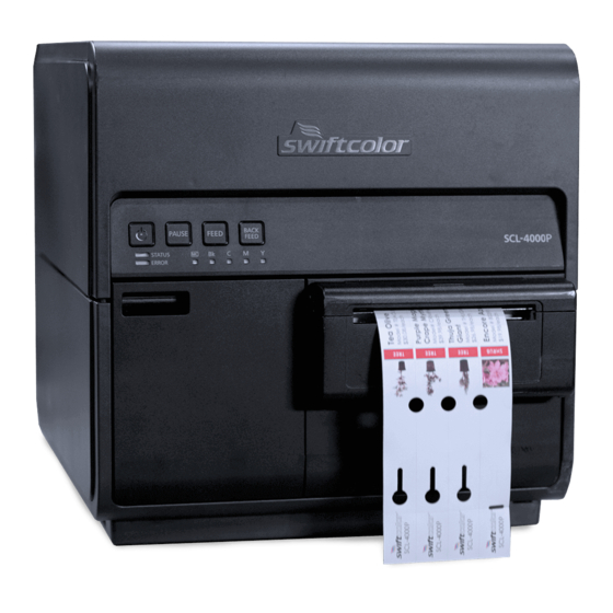
- Page 1 ENGLISH SWIFTCOLOR SCL-4000P Installation Procedure PRINTED IN JAPAN PUB No. 4Y8-8063-020 ENGLISH...
-
Page 2: How To Read This Guide
How to Read This Guide Check Before Installation Installation requirements are listed below. When Using the Included Parts Checking the Power Supply When the parts supplied with this product are required to be used in the installation procedure, the following symbol indicating that the parts are supplied with the product is Power Cord of Printer must be connectable to the outlet (100V to 240V AC -15% to +10%) shown in the illustration. -
Page 3: Installation Precautions
Checking the Installation Space Installation Precautions 1. The minimum space required for installation is shown below. When installing Printer, observe the following precautions: 1) Imaging faults can result due to dew condensation that occurs when the machine is moved 100mm or more 500mm or more from a cold place to a warm place. -
Page 4: Checking The Included Parts
Checking the Included Parts [1] 1 x Printhead Unit [2] 4 x Ink Tank / for starter Scraper [3] 1 x (1 Ink Tank for each color) [4] 1 x Power Cord (for 120V series) [5] 1 x Power Cord (for 230V series) [6] Spare Paper T-1-1 CAUTION:... -
Page 5: Unpacking Procedure
Unpacking Procedure 2) Remove Accessory Box , and then remove Upper Pads. NOTE: Printer is secured using fixing tape and cushioning materials to protect it against the vibrations and shocks applied during transportation. By following the procedure described below, remove all pieces of fixing tape and cushioning materials before installing Printer. - Page 6 4) Holding the handles at the bottom of Printer, lift Printer to take it out from the package 5) Place Printer on a horizontal table, and then remove all pieces of fixing tape and base. cushioning materials visible on the exterior of Printer. 6) Open Roll Cover.
- Page 7 9) Remove fixing tapes and cushioning materials from inside of Printer. NOTE: Keep the removed cushioning materials, because they may be used for future transportation for relocation or repair of Printer. CAUTION: • After ink loading, remove the paper on Transport Unit. •...
-
Page 8: Installation Procedure
Installation Procedure Mounting Printhead Unit 3) Remove the fixing tape, remove Print Module Cover, and then open Lower Printhead Release Lever. 1) Remove 2 screws to remove Maintenance Cover from Upper Unit. F-1-13 F-1-11 2) Close Upper Unit. F-1-14 F-1-12... - Page 9 4) Remove Blade Cleaner. 6) Remove the cover and cushioning materials. F-1-17 F-1-15 5) Take out included Printhead from the package. 7) Remove the 4 caps. F-1-16 F-1-18...
- Page 10 8) Peel the release paper from bundled Scraper. 9) Take Printhead Unit out of the case. CAUTION: Do not touch the area indicated in the following figure. F-1-19 CAUTION: Handle scraper as following figure. F-1-22 CAUTION: • Ink comes out from nozzles of Printhead kept out of the case. Install Printhead immediately after attaching scraper.
- Page 11 10) Attach Scraper to Printhead. 11) Put Printhead Unit on the rail guide, and then insert it into Printer until it stops. CAUTION: Do not touch the area indicated in the following figure. F-1-24 CAUTION: Handle scraper as following figure. F-1-27 NOTE: Skewering Shaft must be on Printhead Guide Rails.
- Page 12 12) Mount Blade Cleaner. 13) Close Lower Printhead Release Lever and Upper Printhead Release Lever. F-1-29 F-1-30 F-1-31...
- Page 13 14) Check that numbers [1] , [2], and [3] indicated on Print Module are visible. 16) Attach Print Module Cover to Print Module. F-1-32 F-1-34 NOTE: If any one of numbers [1] , [2], and [3] is invisible, Printhead Release Lever ( [1] ,[2] )has not been closed or Blade Cleaner ( [3] ) has not been mounted.
- Page 14 Loading Ink Tanks 17) Push down Upper Unit Open Lever, and then open Upper Unit. 1) Open Ink Tank Door. F-1-36 F-1-38 18) Mount Maintenance Cover on Upper Unit. 2) Open Ink Tank Lever for each color while pushing it downward. •...
- Page 15 3) Take out included Ink Tanks from the packages, and then remove the cushioning materials. 5) Slowly insert Ink Tank as far as it will go. CAUTION: Ink Tank cannot be loaded properly if it is inserted in a wrong Ink Tank Slot. F-1-40 4) Shake Ink Tank 2-3 times slowly with the ink supply port facing upward as shown in the figure.
- Page 16 Installing Cutter Unit 7) Set the rest of Ink Tanks and close Ink Tank Door. In the case installing Cutter Unit, follow the installation procedure of Cutter Unit. F-1-44...
- Page 17 Initial Ink Loading 1) Several types of Power Cords come with Printer. Use appropriate Power Cord for the power supply used at the installation site. NOTE: • Initial ink loading takes about 25 minutes. • Ink loading time might be changed due to the design change. CAUTION: •...
-
Page 18: Operation Check
Operation Check After completion of installation, print any image, that is usually used, following the procedure below and check that the printing result is free from faint print and/or color deviation. 1. Install software in Computer and load printing paper that is usually used in Printer. 2.
Need help?
Do you have a question about the SCL-4000P and is the answer not in the manual?
Questions and answers