Table of Contents
Advertisement
Quick Links
Assembly Instructions
Induced Draft, Modular Counterflow Cooling Towers
EVAPCO, Inc. — World Headquarters & Research/Development Center
North America
EVAPCO, Inc.
World Headquarters
P.O. Box 1300
Westminster, MD 21158 USA
410-756-2600 p
|
410-756-6450 f
marketing@evapco.com
EVAPCO East
5151 Allendale Lane
Taneytown, MD 21787 USA
410-756-2600 p | 410-756-6450 f
marketing@evapco.com
EVAPCO East
Key Building
Taneytown, MD USA
410-756-2600 p
marketing@evapco.com
EVAPCO Midwest
Greenup, IL USA
217-923-3431 p
evapcomw@evapcomw.com
EVAPCO West
Madera, CA USA
559-673-2207 p
contact@evapcowest.com
EVAPCO Iowa
Lake View, IA USA
712-657-3223 p
EVAPCO Iowa
Sales & Engineering
Medford, MN USA
507-446-8005 p
evapcomn@evapcomn.com
EVAPCO Newton
Newton, IL USA
618-783-3433 p
evapcomw@evapcomw.com
EVAPCOLD
Greenup, IL USA
217-923-3431 p
evapcomw@evapcomw.com
EVAPCO...S
Rigging and
AT ATLAS
EVAPCO products are manufactured worldwide
P.O. Box 1300 • Westminster, MD 21158 USA
410-756-2600 p • marketing@evapco.com • evapco.com
EVAPCO-BLCT Dry Cooling, Inc.
1011 US Highway 22 West
Bridgewater, NJ 08807 USA
1-908-379-2665 p
info@evapco-blct.com
EVAPCO-BLCT Dry Cooling, Inc.
Littleton, CO 80127 USA
1-908-379-2665 p
info@evapco-blct.com
EVAPCO Power México S. de R.L. de C.V.
Calle Iglesia No. 2, Torre E
Tizapan San Ángel, Del. Álvaro Obregón
Ciudad de México, D.F. México 01090
+52 (55) 8421-9260 p
info@evapco-blct.com
Refrigeration Vessels &
Systems Corporation
A wholly owned subsidiary of EVAPCO, Inc.
Bryan, TX USA
979-778-0095 p
rvs@rvscorp.com
EvapTech, Inc.
A wholly owned subsidiary of EVAPCO, Inc.
Edwardsville, KS USA
913-322-5165 p
marketing@evaptech.com
Tower Components, Inc.
A wholly owned subsidiary of EVAPCO, Inc.
Ramseur, NC USA
336-824-2102 p
mail@towercomponentsinc.com
EVAPCO Alcoil, Inc.
A wholly owned subsidiary of EVAPCO, Inc.
York, PA USA
717-347-7500 p
info@alcoil.net
PECiAliStS in
Visit EVAPCO's Website at:
Europe
EVAPCO Europe BVBA
European Headquarters
Heersterveldweg 19
Industrieterrein Oost
3700 Tongeren, Belgium
|
(32) 12-395029 p
(32) 12-238527 f
evapco.europe@evapco.be
EVAPCO Europe, S.r.l.
Milan, Italy
(39) 02-939-9041 p
evapcoeurope@evapco.it
EVAPCO Europe, S.r.l.
Sondrio, Italy
EVAPCO Europe GmbH
Meerbusch, Germany
(49) 2159 6956 18 p
info@evapco.de
EVAPCO Air Solutions
A wholly owned subsidiary of EVAPCO, Inc.
Aabybro, Denmark
(45) 9824 4999 p
info@evapco.dk
EVAPCO Air Solutions GmbH
Garbsen, Germany
(49) 5137 93875-0 p
info@evapcoas.de
Evap Egypt Engineering Industries Co.
A licensed manufacturer of EVAPCO, Inc.
Nasr City, Cairo, Egypt
2 02 24022866 / 2 02 24044997 p
primacool@link.net / shady@primacool.net
EVAPCO Middle East DMCC
Dubai, United Arab Emirates
+971 4 448 7242 p
info@evapco.ae
EVAPCO S.A. (Pty.) Ltd.
A licensed manufacturer of EVAPCO, Inc.
Isando 1600, Republic of South Africa
(27) 11-392-6630 p
evapco@evapco.co.za
H
t
P
EAt
rAnSfEr
rOduCtS And
evapco.com
Bulletin ATLAS20RIG
Asia/Pacific
EVAPCO Asia/Pacific Headquarters
1159 Luoning Road
Baoshan Industrial Zone
Shanghai 200949, P.R. China
(86) 21-6687-7786 p | (86) 21-6687-7008 f
marketing@evapcochina.com
EVAPCO (Shanghai) Refrigeration Equipment Co., Ltd.
Baoshan Industrial Zone Shanghai, P.R. China
(86) 21-6687-7786 p
marketing@evapcochina.com
Beijing EVAPCO Refrigeration Equipment Co., Ltd.
Huairou District Beijing, P.R. China
010-6166-7238 p
evapcobj@evapcochina.com
EVAPCO Air Cooling Systems (Jiaxing) Company, Ltd.
Building 10, 1133 Taoyuan Road,
Jiaxing, Zhejiang, China
(86) 573 83119379 p
info@evapcoacs.cn
EVAPCO Australia (Pty.) Ltd.
Riverstone NSW 2765, Australia
(61) 2 9627-3322 p
sales@evapco.com.au
EvapTech Asia Pacific Sdn. Bhd
A wholly owned subsidiary of EvapTech, Inc.
Puchong, Selangor, Malaysia
(60-3) 8070-7255 p
marketing-ap@evaptech.com
South America
EVAPCO Brasil
Equipamentos Industriais Ltda.
Al. Vênus, 151 – CEP: 13347-659
Indaiatuba –São Paulo – Brasil
(55+11) 5681-2000 p
vendas@evapco.com.br
Fan Technology Resources
Cruz das Almas – Indaiatuba
São Paulo, Brasil 13308-200
55 (11) 4025-1670 p
fantr@fantr.com
S
.
ErViCES
Advertisement
Table of Contents

Related Manuals for EVAPCO AT ATLAS


Summary of Contents for EVAPCO AT ATLAS
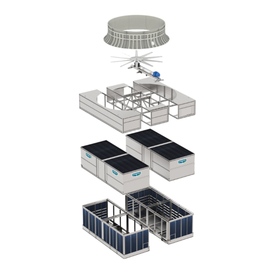
- Page 1 Assembly Instructions AT ATLAS Induced Draft, Modular Counterflow Cooling Towers EVAPCO products are manufactured worldwide EVAPCO, Inc. — World Headquarters & Research/Development Center P.O. Box 1300 • Westminster, MD 21158 USA 410-756-2600 p • marketing@evapco.com • evapco.com North America Europe Asia/Pacific EVAPCO, Inc.
-
Page 2: Table Of Contents
AT ATLAS Induced Draft Counterflow Cooling Towers Table of Contents Introduction................... . 3 Shipping . -
Page 3: Introduction
Shipping Unless otherwise noted in the factory submittal, all EVAPCO AT ATLAS towers ship in seven (7) sections per cell plus the drive system, fan and fan cylinder. Any special shipping configurations will be listed in the factory submittal. Please contact your local EVAPCO representative for more information on alternate shipping configurations. -
Page 4: Structural Steel Support
AT ATLAS Induced Draft Counterflow Cooling Towers Structural Steel Support As standard, three structural “I” beams running the length of the unit are required for support of each cell. These beams should be located underneath the outer flanges of the unit (See Figure 1 and 1a). Transverse steel arrangements are also available (see Figures 1b and 1c). -
Page 5: Rigging Basin Sections
AT ATLAS Induced Draft Counterflow Cooling Towers Rigging Basin Sections Lifting devices are located along the inside edges of the bottom section for lifting and final positioning purposes as shown in Figure 2. The hook of the crane must be a minimum dimension of 26’ above the top of the basin section to prevent undue strain on the lifting devices. - Page 6 AT ATLAS Induced Draft Counterflow Cooling Towers 5. Repeat steps 2-4 for all 3 flume boxes. 6. Rig the second basin adjacent to the equalizer flume on the steel support as shown in Figure 3. 7. Clean the mating surfaces of the flume box and the surface of the flume opening on the adjacent section. Apply sealer tape to the flanged flume opening on the adjacent section.
-
Page 7: Application Of Sealer Tape To Basin Sections
AT ATLAS Induced Draft Counterflow Cooling Towers DRIP CHANNEL TAPPERS (GALVANIZED) 5/16" OR STAINLESS STEEL HARDWARE BOLTS (STAINLESS) SEALER TAPE RETAINING CLIP DRILLING IS REQUIRED IN THE FIELD FOR THESE HOLES DRIP CHANNEL SIDE PANEL SECTION Figure 3a - Drip Channel and Vertical Splash Guard Installation... -
Page 8: Rigging Casing Sections
AT ATLAS Induced Draft Counterflow Cooling Towers Rigging Casing Sections Lifting ears are provided in the corners of the casing sections and along the length (4 total lifting ears per side) for lifting and final positioning. The hook of the crane must be a minimum dimension 26’ above the casing sections to prevent undue strain on the lifting ears. - Page 9 The side flanges located in between cells can be accessed from inside the unit. Bolts can be driven upward through the mating flanges if access is restricted. All rigging hardware is provided by EVAPCO. Drift pins are by others. The recommended drift pin is 3/16” punch size with 10” overall length.
-
Page 10: Assembly Of Bottom Inlet Piping
AT ATLAS Induced Draft Counterflow Cooling Towers Assembly of Bottom Inlet Piping On the ATLAS tower, the inlet connection is located on the bottom as standard. Internal piping is provided that allows the process water to make its way to the hot water distribution system. Please follow the below steps to complete field installation of the bottom inlet after the unit is rigged. -
Page 11: Application Of Sealer Tape To Casing Sections
AT ATLAS Induced Draft Counterflow Cooling Towers Application of Sealer Tape to Casing Sections Once the casing sections have been rigged to the basin sections and all fasteners are installed, the top flanges should be wiped down to remove any dirt or moisture. Apply one layer of sealer tape, centered over the mounting holes (see Figure 9). On the flanges between casing sections, apply two strips of sealer tape, one partially overlapping the other on the entire length of the flanges. -
Page 12: Rigging Fan Sections
AT ATLAS Induced Draft Counterflow Cooling Towers Rigging Fan Sections Each ATLAS unit has 3 fan sections: left, right and middle. On the middle section, lifting ears are provided for lifting and final positioning. For the left and right sections, “U” bolts are provided. The hook of the crane must be a minimum of 26’ above the lifting device to prevent undue strain on the lifting ears and “U”... -
Page 13: Assembly Of The Fan Sections To The Casing Sections
AT ATLAS Induced Draft Counterflow Cooling Towers Assembly of the Fan Sections to the Casing Sections The fan sections rigging should begin with an end fan module, followed by the middle fan module and finally followed by the last end fan module. -
Page 14: Rigging Fan Sections On Multicell Units
AT ATLAS Induced Draft Counterflow Cooling Towers Rigging Fan Sections on Multicell Units In multicell installations, placing multiple towers side-by-side will limit access between cells and make rigging more difficult. Therefore multicell rigging channels will come attached to the inside of the casing and fan section panels, as shown in Figure 12. -
Page 15: Fan Sealing
AT ATLAS Induced Draft Counterflow Cooling Towers Fan Sealing After rigging, apply caulk to the top and end seams of the fan sections (Figure 13). This must be done from the inside of the unit. APPLY CAULK TO FAN SECTION TOP AND END... -
Page 16: Floating Shaft Installation & Alignment
AT ATLAS Induced Draft Counterflow Cooling Towers Floating Shaft Installation & Alignment The fan motor and gear reducer will ship mounted to the mechanical equipment support. The system will be prealigned in the factory, however alignment should be verified prior to rigging the mechanical equipment support to the fan section. -
Page 17: Fan Assembly Instructions
AT ATLAS Induced Draft Counterflow Cooling Towers Fan Assembly Instructions Once the gear drive has been aligned the fan should be assembled onto the mechanical equipment assembly. This simplifies assembly by completing it at ground level and reducing the number of lifts required. -
Page 18: Rigging Drive Assembly
AT ATLAS Induced Draft Counterflow Cooling Towers Rigging Drive Assembly Once the gear drive has been aligned and the fan assembled onto the gear output shaft, the entire assembly should be lifted onto the fan section (Figure 17). The hook of the crane must be a minimum of 17’ above the lifting ears. See Table 8 for hardware required to attach the drive assembly to the fan deck. -
Page 19: Fan Cylinder Assembly
AT ATLAS Induced Draft Counterflow Cooling Towers Fan Cylinder Assembly The fan cylinder will ship in 10 sections for assembly and installation in the field. Each section will be joined with a flange as shown in Figure 18. Fan cylinder assembly should be performed on the ground with one person holding the sections up until the assembly is able to stand alone. -
Page 20: Fan Cylinder Rigging
AT ATLAS Induced Draft Counterflow Cooling Towers Fan Cylinder Rigging Lower cylinder carefully around fan and drive shaft using the provided lifting ears. The hook of the crane must be a minimum of 17’ above the lifting ears. Make sure fan assembly is centered within the cylinder before attaching to fan section. Measure the clearance between each fan tip and the cylinder with a tape measure, making sure it is 7/8”... -
Page 21: Fan Cylinder Sealing
AND FAN SECTIONS Figure 20 - Fan Cylinder Sealing After fan, drive system and fan cylinder are entirely assembled, rigged and sealed, the fans must be balanced per the fan manufacturer’s procedure. Contact your local EVAPCO representative for more information. -
Page 22: External Platform And Vertical Ladder Installation
AT ATLAS Induced Draft Counterflow Cooling Towers External Platform and Vertical Ladder Installation If your unit is accessorized with an external service platform assembly with a vertical ladder, this equipment is shipped in the basin of your unit. In some cases, they are shipped separately due to other basin accessories that may interfere with storage. The platform is partially assembled prior to shipment to minimize field assembly. - Page 23 AT ATLAS Induced Draft Counterflow Cooling Towers FITTINGS ON LADDER MAY NEED TO BE ADJUSTED IN FIELD. FAN DECK ACCESS LADDER FITTINGS ON LADDER MAY CASING MOUNTED NEED TO BE ADJUSTED PLATFORM IN FIELD. CUT TIE WRAPS ON LADDER BRACKETS AND INSTALL LADDER MOUNTED USING SUPPLIED 3/8”...
- Page 24 EVAPCO, Inc. • P.O. Box 1300 • Westminster, MD 21158 USA Phone: 410-756-2600 • Fax: 410-756-6450 • E-mail: marketing@evapco.com Printed on recycled paper ©2020 EVAPCO, Inc. using soy-based ink...
Need help?
Do you have a question about the AT ATLAS and is the answer not in the manual?
Questions and answers