Advertisement
Quick Links
No: 341100 – 10/14
Catalog Number: WSP251
Country of Origin: Made in China
SPECIFICATIONS
Voltages ........................................................... 120 or 277VAC, 50/60Hz
Load Requirements
@ 120VAC ...........0~1000W ballast, E‑ballast, LED, tungsten, 1/4 hp
@ 277VAC ...................... 0~1200W ballast, E‑ ballast & LED, 1/4 hp
Common Features
Time Delay Adjustment ....................................30 seconds ‑ 30 minutes
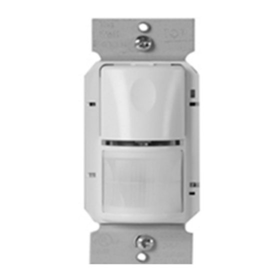
UNIT DESCRIPTION AND OPERATION
The WSP251 PIR Wall Switch Occupancy Sensors turn lighting or fan loads ON and
OFF based on occupancy and ambient light level. They are designed to replace a
standard light switch. The WSP251 operates with 120 or 277VAC line voltage.
The sensor uses passive infrared technology to sense human motion, and defines
it as occupancy. A red LED on the sensor blinks upon occupancy and then resets.
It will blink again when it detects motion after the 2‑second reset.
The sensor turns ON the load automatically when it detects occupancy. Once the
space is vacant and the time delay elapses, it turns OFF the load automatically.
If adequate ambient light is already present in the area, the sensor will hold OFF the
load it controls. When the light drops below a field selectable level and the sensor
detects occupancy, the sensor turns ON the load. Once turned ON, the load remains
ON until the space is vacant or the light level rises above the setpoint and the time
delay expires.
Manual Operation: The occupant can
press the ON/OFF button to turn the load
ON and OFF. When the load is turned
ON manually, the sensor will keep the
load ON until no motion is detected for
the length of the time delay. If the load
is turned OFF manually, the sensor
holds the load OFF until no motion
has been detected for the duration of
5 minutes. The next time the sensor
detects occupancy and the ambient light
is lower than the set level, the sensor
automatically turns ON the load.
Walk‑test feature:
When the Time Delay trimpot is in
the fully counterclockwise position, the
sensor has a 30 second time delay.
This allows you to quickly check the
sensor coverage area.
Service function:
In the event of unit failure or if it is necessary to leave the load ON, remove the Service
Jumper plug. This disables all automatic ON and OFF functions and the load can only
be operated using the ON/OFF button.
COVERAGE PATTERNS
The WSP detects motion in areas up
to 900 sq. ft. and up to 35 feet from the
sensor. Ideally, the sensor is designed
for small amounts of motion in spaces
up to 300 sq. ft. The Fresnel lens on the
sensor is a multiple segment viewing
lens with a field of view of 180°.
The sensor must have a clear view
of the people in the space in order to
detect occupancy. Obstructions, such as
furniture blocking the sensor's lens, may
prevent occupancy detection.
Top View
4.0'
(1.2m)
floor
Side View
Press down
on tab and
pry off Cover
ON/OFF
Switch
Service
Jumper
(L)
Light Level
Time Delay
(T)
Sensitivity
(S)
ON/OFF Button
LED
(Switch Cover)
Fresnel Lens
Maximum = clockwise
Minimum = counterclockwise
(10.7m)
15'
(4.6m)
(10.7m)
Pass & Seymour
Passive Infrared Wall Switch Occupancy Sensor
Installation Instructions
Sensitivity Adjustment .............................................. Minimum‑Maximum
Light Level Adjustment ...............................................0‑200fc (@4000K)
Operating Temperature ..................................................... 40°C (104°F)
Storage Temperature ......................................................... 70°C (158°F)
Terminal screw torque ............................................. 16 lbf‑in (18 kgf‑cm)
Optional Neutral Connection
MASKING THE LENS
Opaque adhesive tape is supplied so that sections of the
sensor's view can be masked. This allows you to eliminate
coverage in unwanted areas.
Since masking removes bands of coverage, remember to take
this into account when troubleshooting coverage problems.
INSTALLATION
Turn the power OFF at the circuit breaker
1. Connect the existing wires in the wall box to the sensor flying leads. (See Wiring
Directions).
• Do not allow bare wire to show below connector.
• The ground wire must be tightly grounded for the unit to operate properly.
2. Attach the sensor to the wall by mounting it in the wall box with the two mounting
screws provided.
3. Turn ON power at the circuit breaker.
4. Test the sensor using the procedure in the Sensor Adjustments section.
There is an initial warm‑up period after installation. It may take up to a minute
before the load turns ON due to a sensor warm‑up period during initial power‑up
(this occurs during installation only). The load turns ON after the warm‑up period
ends if the sensor detects motion.
Rapid successive pressing of the ON/OFF button causes a delay in function.
A single press of the button causes an immediate response. If the button is pressed
again within 2 seconds, the switch ignores it if there is not enough power. Wait at
least two seconds between button presses.
5. Install industry standard decorator wall switch cover plate (not included).
OPTIONAL NEUTRAL WIRING
For applications requiring neutral wiring, remove tab as shown
to expose terminals for wiring.
35'
Breakaway
tab
35'
®
CAUTION
before installing the sensor.
6" flying leads
for line, load and
ground connections
Optional neutral
terminals behind
breakaway tab
Opaque tape
Strip Gage
1/2"
12.7 mm
Copper Wire Only
#12 – #14 AWG
Advertisement

Related Manuals for LEGRAND Pass & Seymour WSP251


Summary of Contents for LEGRAND Pass & Seymour WSP251
- Page 1 Pass & Seymour ® Passive Infrared Wall Switch Occupancy Sensor No: 341100 – 10/14 Installation Instructions Catalog Number: WSP251 Country of Origin: Made in China SPECIFICATIONS Voltages ............120 or 277VAC, 50/60Hz Sensitivity Adjustment ..........Minimum‑Maximum Load Requirements Light Level Adjustment ..........0‑200fc (@4000K) @ 120VAC ...0~1000W ballast, E‑ballast, LED, tungsten, 1/4 hp Operating Temperature .............
- Page 2 PURPOSE, ARE LIMITED TO A PERIOD OF TWO YEARS FROM THE BE LIABLE FOR LOST PROFITS, INDIRECT, SPECIAL, EXEMPLARY, the device for replacement to the store where purchased or send to: Legrand, DATE OF PURCHASE. YOUR SOLE AND EXCLUSIVE REMEDY AGAINST INCIDENTAL OR CONSEQUENTIAL DAMAGES.
Need help?
Do you have a question about the Pass & Seymour WSP251 and is the answer not in the manual?
Questions and answers