Table of Contents
Advertisement
Quick Links
SigTEL (1 to 16 Lines) Standalone EVCS - Quick Start Installation Guide
THIS GUIDE IS ONLY FOR EXPERIENCED INSTALLERS OF EMERGENCY VOICE COMMUNICATION SYSTEMS (EVCS) and summarises key information provided in the full manual (Document No.
DAU0000091). Section numbers, e.g.
SigTEL EV S Typical Wiring Overview
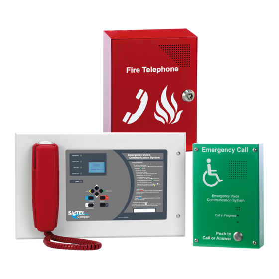
EVC302F
NC951
Fig 1
NC951 lines: 2-core
enhanced fire rated cable.
Outstation lines: 2-core enhanced
2
fire rated cable (1.0 to 1.5 mm
, up
)
to 1 km in length.
Power supply: Fixed wiring, 2-core
2
enhanced fire rated cable (0.75 mm
2
to 2.5 mm
) fed from a switched spur,
fused at 3 amps.
4 x Extension Lines from Outstations & NC951
All screens connect
to Earth terminal
I/P A I/P B I/P C
+ - + - + -
+ - + -
+ - + -
L1
L2
L3
L4
ECU-4
Exchange PCB
A
B
C D
8 x Extension Lines from Outstations & NC951
Fig 2
All screens connect
I/P A I/P B I/P C
+ - + - + -
+ - + -
+ - + -
+ - + -
+ - + -
L1
L2
L3
L4
L5
L6
L7
L8
ECU-8 or ECU-8NT or ECU-8S
Exchange PCB
A
B
C D
SigT L
Emergency Voice
Communication System
6.1
, reference sections in the full manual with additional information.
EVC302GS
EVC301RPO
Master/Slave connection:
Mount slave adjacent to
the master.
additional
8 x
extensions
extension lines
* ECU-8 has eight available
extension lines, ECU-4 (not
F U S E
shown) has four.
3A fused spur
Wiring and Cable Entry
N/O C N/C 0V +24 OP3 OP2 OP1
See Fig 1 above for cable types. Install wiring in accordance with the relevant national, regional or local regulations (in the UK this is the IEE
Wiring Regs BS 7671 and BS 5839 Part 1. Use enhanced fire-rated cables from the controller to the outstations / NC951 and the power supply.
Test Extension Lines
Test all lines for faults before terminating extension lines to the control unit. Also, test outstation lines using a FITT EVC line tester (see
component list above).
CAUTION: DO NOT use an Insulation Resistance Tester with any devices connected as they will be destroyed and the warranty will be void.
Fit Outstations & NC951 Interface
to Earth terminal
Maximum recommended cable distance to the outstations is 1 km, beyond which audio quality may degrade. For wiring and connection details
N/O C N/C 0V +24 OP3 OP2 OP1
refer to Type A outstation instructions (Doc. No. DCM0003819) and Type B outstation instructions (Doc. No. DAU0302000).
Connect Extension Lines to the Control Equipment
Do not connect extension lines to the ECU-4/ECU-8, or optional ECU-8S, until they have been tested, fault-free and suitable cable glands fitted.
Connect extension lines directly to the Exchange PCB (see Fig 2 left). Connect screens to the earth terminal in the back of the enclosure.
Approved Document No. DAU0000093 Rev 2
Part No.
ECU-4
ECU-8
ECU-8NT
ECU-8S
EVC302F/GF
EVC302S/GS
EVC301RPO
EVC301RLK
BF359/1
BF359/3D
NC951
FITT
BC286/2
AFP385
Install the EV S
T-BEZ301
ECU423
Location
6.1
Site all equipment indoors in well-lit areas, free from obstruction. If background noise exceeds 40 dBA,
use an acoustic hood. Site control unit(s) in the control room or lobby, 1.4 metres above final floor level
(FFL). Fit Type A (fire telephone) outstations in fire fighting lobbies and fire access points, 1.3 to 1.4
metres above FFL. Fit type B (disabled refuge) outstations in disabled refuges, 0.9 to 1.0 metre above FFL.
Mounting
7
Remove base PCBs before first fix installation to protect them and expose the base mounting holes.
Wall mount the control units, either surface or semi-flush. Fix the base securely onto a wall using No.8
round-head, or countersunk screws. If an optional ECU-8S is fitted make the interconnections to the
ECU-4/ECU-8 using supplied looms and short length of steel conduit (25 mm OD, max. length 60 mm).
After mounting, remove any dust/swarf and re-install base PCBs. Ensure all connecting looms are refitted.
4
12
11
13.1
SigTEL EVCS Components
Description
4 Line Master EVC Controller c/w handset & display, needs 2 x 7 Ah batteries
8 Line Master EVC Controller c/w handset & display, needs 2 x 7 Ah batteries
8 Line Master EVC Controller (no handset) c/w display, needs 2 x 7 Ah batteries
8 Line Slave EVC Expansion Unit (adds 8 extra lines to ECU-4, ECU-8, ECU-8NT)
Disabled Refuge (Type B) Outstation, flush mounting, SS ('G' - Green steel)
Disabled Refuge (Type B) Outstation, surface mounting, SS ('G' - Green steel)
Red Fire Telephone (Type A) Outstation c/w handset (push to open)
Red Fire Telephone (Type A) Outstation c/w handset (lift lock)
Weatherproof enclosure for EVC302F/GF
Stainless steel enclosure for ECU-4/ECU-8/ECU-8NT
Disabled Persons Toilet Alarm (DPTA)
EVC Line Tester
24 V, 7 Ah battery (2 x 12 V) used with ECU-4/ECU-8/ECU-8NT
Grey flush bezel for ECU-4/ECU-8/ECU-8NT
Red flush bezel for EVC301RPO and EVC301RLK
PC programming software
1 of 2
Advertisement
Table of Contents

Related Manuals for SigTEL EVCS

Summary of Contents for SigTEL EVCS
- Page 1 SigTEL (1 to 16 Lines) Standalone EVCS - Quick Start Installation Guide THIS GUIDE IS ONLY FOR EXPERIENCED INSTALLERS OF EMERGENCY VOICE COMMUNICATION SYSTEMS (EVCS) and summarises key information provided in the full manual (Document No. DAU0000091). Section numbers, e.g.
- Page 2 Contact your supplier for details. Configure the system 17.1 Using the ECU-4/ECU-8 keypad DO NOT press the Press Engineer Mode button EVCS (located back of ECU-4/ECU-8 lid) Reset button! Check the unit count Check number of ECU-4 Press END button...
Need help?
Do you have a question about the EVCS and is the answer not in the manual?
Questions and answers