Table of Contents

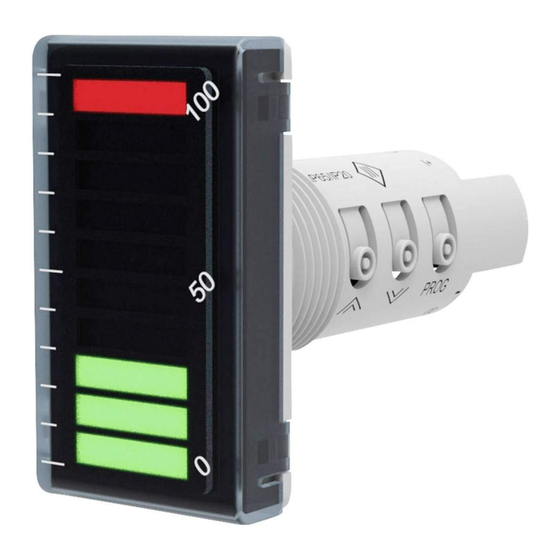
Summary of Contents for Akytec ITP15
- Page 1 ITP15 LED Bargraph Indicator User guide ITP15_2019.12_48199_EN © All rights reserved Subject to technical changes and misprints akYtec GmbH · Vahrenwalder Str. 269 A · 30179 Hannover · Germany · Tel.: +49 (0) 511 16 59 672-0 · www.akytec.de...
-
Page 2: Table Of Contents
Maintenance ..............................8 Transportation and storage ......................... 8 Scope of delivery ............................9 Appendix A. Dimensions ............................ 9 akYtec GmbH · Vahrenwalder Str. 269 A · 30179 Hannover · Germany · Tel.: +49 (0) 511 16 59 672-0 · www.akytec.de... -
Page 3: Overview
-25…+55 °C Storage temperature IP Code front IP65, rear IP20 Protection class up to 80% (at +35°C, non-condensing) Relative humidity akYtec GmbH · Vahrenwalder Str. 269 A · 30179 Hannover · Germany Tel.: +49 (0) 511 16 59 672-0 · www.akytec.de... -
Page 4: Intended Use
To connect fine-stranded wire, tin the wire To connect stranded wire, press the release end. lever and push the wire into the terminal. akYtec GmbH · Vahrenwalder Str. 269 A · 30179 Hannover · Germany Tel.: +49 (0) 511 16 59 672-0 · www.akytec.de... -
Page 5: Input
As a precaution against inadvertent current reversal on output, a parallel diode (U NOTICE ≥ 1.3U, I ≥ 1.3I) is usually included in the output circuit. Fig. 5.6 NPN transistor output akYtec GmbH · Vahrenwalder Str. 269 A · 30179 Hannover · Germany Tel.: +49 (0) 511 16 59 672-0 · www.akytec.de... -
Page 6: Configuration
All parameters and its values are explained in Table 6.2. Default values are highlighted in bold. Table 6.2 Configuration parameters Display Name Value 4-20 mA Signal type 0-20 mA akYtec GmbH · Vahrenwalder Str. 269 A · 30179 Hannover · Germany Tel.: +49 (0) 511 16 59 672-0 · www.akytec.de... -
Page 7: Alarm Limits
To set up the upper (HL) and lower (LL) limits, press and hold the button for 3 seconds and then proceed in accordance with Fig. 6.3. Fig. 6.2 Output control akYtec GmbH · Vahrenwalder Str. 269 A · 30179 Hannover · Germany Tel.: +49 (0) 511 16 59 672-0 · www.akytec.de... -
Page 8: Operation
When the input signal is connected and the supply voltage is turned on, the display shows the process value as shown in Fig. 7.1. akYtec GmbH · Vahrenwalder Str. 269 A · 30179 Hannover · Germany Tel.: +49 (0) 511 16 59 672-0 · www.akytec.de... -
Page 9: Maintenance
Check the device for transport damage and completeness! Report the transport damage immediately to the shipper and akYtec GmbH! akYtec GmbH · Vahrenwalder Str. 269 A · 30179 Hannover · Germany Tel.: +49 (0) 511 16 59 672-0 · www.akytec.de... -
Page 10: Scope Of Delivery
To prevent the device spinning, the borehole in the front panel must correspond to the dimensions in Fig. A2. akYtec GmbH · Vahrenwalder Str. 269 A · 30179 Hannover · Germany Tel.: +49 (0) 511 16 59 672-0 · www.akytec.de...


Need help?
Do you have a question about the ITP15 and is the answer not in the manual?
Questions and answers