
Related Manuals for Cincoze GP-3000 Series


Summary of Contents for Cincoze GP-3000 Series
- Page 1 GP-3000 Series User Manual Embedded GPU Computer /Core™ Modular GPU Computer, ® ® 9/8th Gen Intel Xeon Supports Dual Full-length GPU Expansion Up to 500W Version: V1.00...
-
Page 2: Table Of Contents
3.5 Installing M.2 M Key Card ....................49 3.6 Installing Antenna ......................50 3.6.1 Antenna #1 to #4 ....................50 3.6.2 Antenna #5 to #7 ....................52 3.7 Installing Thermal Pad on MOSFET Heatsink ..............54 GP-3000 Series | User Manual... - Page 3 4.6.1 Setup Prompt Timeout [1] ..................88 4.6.2 Bootup NumLock State [Off] ................... 88 4.6.3 Quiet Boot [Disabled] ....................88 4.6.4 Fast Boot [Disabled] ....................88 4.7 Save & Exit ........................89 4.7.1 Save Changes and Exit ..................89 GP-3000 Series | User Manual...
- Page 4 6.4.3 CFM-IGN03-R11 Module ..................144 6.5 Installing MEC Module ....................145 6.5.1 MEC-USB-M102-15/UB1414 Module ..............145 6.6 Installing GEB-3301-R10 Module ................... 148 6.6.1 Installing GEB-3301-R10 Module onto GP-3000 ........... 148 6.6.2 Installing GPU Card ....................151 GP-3000 Series | User Manual...
- Page 5 6.7.3 Installing Rubber Foot Pad ................... 175 6.7.4 Installing Wall Mount ..................... 177 6.8 Power Supply Cabling Guide..................179 6.8.1 Cabling with US Power Cord ................. 179 6.8.2 Cabling with EU Power Cord ................. 181 GP-3000 Series | User Manual...
-
Page 6: Preface
2021/01/27 Copyright Notice © 2021 by Cincoze Co., Ltd. All rights are reserved. No parts of this manual may be copied, modified, or reproduced in any form or by any means for commercial use without the prior written permission of Cincoze Co., Ltd. All information and specification provided in this manual are for reference only and remain subject to change without prior notice. -
Page 7: Product Warranty Statement
Product Warranty Statement Warranty Cincoze products are warranted by Cincoze Co., Ltd. to be free from defect in materials and workmanship for 2 years from the date of purchase by the original purchaser. During the warranty period, we shall, at our option, either repair or replace any product that proves to be defective under normal operation. - Page 8 Before sending your product in, you will need to fill in Cincoze RMA Request Form and obtain an RMA number from us. Our staff is available at any time to provide you with the most friendly and immediate service. ◼...
-
Page 9: Technical Support And Assistance
Technical Support and Assistance 1. Visit the Cincoze website at www.cincoze.com where you can find the latest information about the product. 2. Contact your distributor or our technical support team or sales representative for technical support if you need additional assistance. Please have following information ready before you call: ⚫... -
Page 10: Safety Precautions
The equipment has obvious signs of breakage. 14. CAUTION: Danger of explosion if battery is incorrectly replaced. Replace only with the same or equivalent type recommended by the manufacturer. 15. Equipment intended only for use in a RESTRICTED ACCESS AREA. GP-3000 Series | User Manual... -
Page 11: Ordering Information
Full-length GPU Expansion Up to 500W Package Checklist Q’ty Item Description Wall Mount Bracket Desktop Mount Kit CPU Heat Sink and Thermal Pad Screws Pack Rubber Foot Kit Power Terminal Block Connector Remote Function Terminal Block Connector Utility DVD Driver GP-3000 Series | User Manual... - Page 12 Available Models Model No. Product Description GPU Expansion Box with 2 x PCIe x 16 (Signal PCIe x 8), 1 x PCIe x 4 GEB-3601-R10 and 1 x PCIe x 1 Slots for GP-3000 Series Package Checklist Q’ty Item Description...
-
Page 13: Chapter 1 Product Introductions
Chapter 1 Product Introductions GP-3000 Series | User Manual... -
Page 14: Overview
1.1 Overview GP-3000. A flagship GPU edge computing computer of Cincoze. Its crowning feature is an exclusive GPU Expansion Box that provides expansion for up to two high-end GPU cards and creating a high-performance industrial-grade GPU computing computer. Extreme Computing Performance The GP-3000’s extreme computing power starts with an 8th or 9th generation Intel®... -
Page 15: Highlights
Upgrades become easier, and Expansion Box (GEB) design can flexibly the expansion possibilities become almost expand up to dual high-end GPU cards. endless. And GP-3000 offers 720W system power budget for high-end GPU Computing applications. GP-3000 Series | User Manual... -
Page 16: Product Pictures
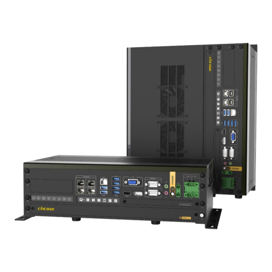
1.3 Product Pictures GP-3000 GP-3000 Series | User Manual... - Page 17 GP-3000/GEB-3301 GP-3000 Series | User Manual...
- Page 18 GP-3000/GEB-3601 GP-3000 Series | User Manual...
-
Page 19: Key Features
Supports 2 x PCIe x16 Slots for full-length GPU cards Expansion ⚫ Supports 1 x PCIe x4 Slot and 1 x PCIe x1 slot for Add-on cards ⚫ Intelligent Cooling Design for High Performance GPU Card ⚫ Military Standard Shock & Vibration Proof (pending) GP-3000 Series | User Manual... -
Page 20: Hardware Specification
• MEC Module - GbE4: Intel® I210-IT Optional Modules: - GbE5: Intel® I210-IT - 2x 5Gbps USB 3.2 Gen1, Type A • 2x RS-232/422/485 with Auto Flow Control (Support 5V/12V), DB9 - 2x GbE LAN, RJ45 GP-3000 Series | User Manual... - Page 21 • Storage Temperature: -40°C to 85°C • Relative Humidity: 95% RH @ 70°C (Non-condensing) • Shock: MIL-STD-810G (pending) • Vibration: MIL-STD-810G (pending) • EMC: CE, FCC, ICES-003 Class A, EN50121-3-2 (Railway), E-mark • Safety: LVD (EN62368-1) • MTBF: 441,283 hr GP-3000 Series | User Manual...
- Page 22 • 4x 8-Pin Connector for GPU Card Connector • 500W Total Power Budget • 5.2 kg Weight Information • 200 x 195 x 360 mm Dimension (W x D x H) • 1,661,177 hr MTBF GP-3000 Series | User Manual...
-
Page 23: System I/O
A terminal block used to connect to remote reset Used to connect the system with VGA monitor switch Display Port DC IN Used to connect a monitor with DisplayPort Used to plug a DC power input with terminal interface block GP-3000 Series | User Manual... - Page 24 Used to insert 2.5” SATA HDD/SSD Used to select AT or ATX power mode Clear CMOS Battery Clear CMOS Used to insert CMOS battery Used to clear CMOS for BIOS reset IGN Setting Switch Used to set up IGN function GP-3000 Series | User Manual...
- Page 25 External Fan Used to be system’s external fan GP-3000 Series | User Manual...
-
Page 26: Mechanical Dimension
1.7 Mechanical Dimension GP-3000 Unit: mm GEB-3301 Unit: mm GP-3000 Series | User Manual... - Page 27 GEB-3601 Unit: mm GP-3000 Series | User Manual...
-
Page 28: Chapter 2 Switches & Connectors
Chapter 2 Switches & Connectors GP-3000 Series | User Manual... -
Page 29: Location Of Switches And Connectors
2.1 Location of Switches and Connectors 2.1.1 Top View 2.1.2 Bottom View GP-3000 Series | User Manual... -
Page 30: Switches And Connectors Definition
GPIO / PoE Function / SATA HDD / System Power LED POWER1, POWER2 +5V/+12V power output connector SODIMM1, SODIMM2 DDR4 SO-DIMM USB2_1_DB Internal USB 2.0 Ports USB2_13_1 Internal USB 2.0 Ports USB3_1 USB3.2 Gen2 Port x2 / USB3.2 Gen1 Port x2 VGA1 VGA connector GP-3000 Series | User Manual... -
Page 31: Definition Of Switches
Definition Left AT Power Mode Right ATX Power Mode (Default) CLR_CMOS1_1:Clear CMOS Switch Switch Definition Left Clear CMOS Right Normal (Default) PWR_SW1:Power Button Switch Definition Push Power System RESET1_1:Reset Switch Switch Definition Push Reset System GP-3000 Series | User Manual... - Page 32 SW1:Super CAP SW and COM1~2 with Power Select Location Function DIP1 DIP2 Enabled ON (Default) Super ON (Default) Disabled Location Function DIP3 DIP4 0V (RI) ON (Default) ON (Default) COM1 Location Function DIP5 DIP6 0V (RI) ON (Default) ON (Default) COM2 GP-3000 Series | User Manual...
-
Page 33: Definition Of Connectors
RESERVED PETN0 1.5V SMB_DATA CLKREQ# PETP0 RESERVED RESERVED USB_D- REFCLK- RESERVED RESERVED USB_D+ REFCLK+ RESERVED RESERVED RESERVED RESERVED LED_WWAN# RESERVED RESERVED LED_WLAN# RESERVED RESERVED RESERVED LED_WPAN# RESERVED PERST# +1.5V PERN0 RESERVED +3.3VAUX PERP0 RESERVED +3.3V GP-3000 Series | User Manual... - Page 34 WGR_D1N PETP0 WTD1P/PETN1 RBI_DT PCM_SYNC/LPCRSTN WGR_D1N PETN0 PCM_IN CLINK_REST REF_CLK WTD0N/PETP1 PCM_OUT CLINK_DATA WGR_D0N PERP0 WTD0P/PERN1 CLINK_CLK WGR_D0P PERN0 COEX3 PEWAKE1# WTCLK/REFCLKP1 UART_WAKE COEX_TXD +3.3V WGR_CLKN REFCLKP0 WTCLK/REFCLKN1 BRI_RSP COEX_RXD +3.3V WGR_CLKP REFCLKN0 SUSCLK PERST0# GP-3000 Series | User Manual...
- Page 35 CN5:Mini PCI-Express Socket (Support mPCIe / USB3 / SIM Module) Definition Definition WAKE# VCC3SB_MPCIE3 +1_5VRUN SMB_CLK PCIE_TXN1 +1_5VRUN SMB_DATA P_UIM_RST2 PCIE_TXP1 P_UIM_PWR P_UIM_DATA USB2_CON_N8 CLKC_MIN3_N P_UIM_CLK USB2_CON_P8 CLKC_MIN3_P VCC3SB_MPCIE3 P_UIM_RST VCC3SB_MPCIE3 P_UIM_VPP P_UIM_CLK2 P_UIM_DATA2 VCC3SB_MPCIE3 MPCIE1_RST# +1_5VRUN PCIE_RXN1 VCC3SB_MPCIE3 PCIE_RXP1 VCC3SB_MPCIE3 GP-3000 Series | User Manual...
- Page 36 REFCLKP 3.3V PERN3- PERP1 PERP3 SUSCLK PETN1 PEDET/CFG1 DAS/DSS* 3.3V PETN3 PETP1 3.3V DEVSLP 3.3V PETP3 3.3V SMB_CLK 3.3V PERN0/SATA_B+ CFG2 3.3V SMB_DATA PERN2 PERP0/SATA_B- 3.3V ALERT# PERP2 CFG0 PETN0/SATA_A- PETN2 PETP0/SATA_A+ PERST*/NC PETP2 CLKREQ*/NC GP-3000 Series | User Manual...
- Page 37 DC_IN1:3 PINs x2 DC 9-48V power input with power ignition connector Connector Type: 2x 3-pins Terminal Block , 5.0mm pitch Definition 9_48VSB_IN 9_32VSB_ACC (IGN) 9_48VSB_IN Chassis GND 1 2 3 Warning!!! Only Single Power Source can connect to DC_IN1. GP-3000 Series | User Manual...
- Page 38 No activity PoE module detected Green PoE Function LED PoE module not detected Data activity Blinking Yellow HDD LED No activity Power on Green System Power LED Standby Blinking Green and Blue Power off Blue GP-3000 Series | User Manual...
- Page 39 4 3 2 1 +VCC12 POWER2 (FAN IN Control):CPU thermal sensor for CPU smart fan Connector Type: 1x4 4-pin Wafer, 2.0mm pitch Definition 4 3 2 +VCC12 POWER1 (FAN OUT Control) POWER2 (FAN IN Control) GP-3000 Series | User Manual...
-
Page 40: Chapter 3 System Setup
Chapter 3 System Setup GP-3000 Series | User Manual... -
Page 41: Removing Top Cover
3.1 Removing Top Cover 1. Loosen the 4 screws on the top plate and then remove the top plate. 2. Loosen the 2 screws on the top cover. GP-3000 Series | User Manual... - Page 42 3. Loosen the 6 screws on the side and rear panel of the system. 4. Remove the top cover from the chassis. GP-3000 Series | User Manual...
- Page 43 5. Place the top cover aside gently. Warning: During the following entire installation procedures, please be careful not to touch the pins on the fan power connector. Otherwise, the fan power connector will be damaged and may not work properly. GP-3000 Series | User Manual...
-
Page 44: Installing Cpu
Pull aside and then lift up the socket lever to unlock the socket. Align the notches on the CPU with protrusions on the socket. Hold the CPU by the edges and put on the CPU gently. GP-3000 Series | User Manual... - Page 45 3 of chapter 3.8. Place the thermal pad on the CPU heat sink. Note: Before assembling the system’s chassis cover, please make sure the transparent protective film on the Thermal Pad has been removed! GP-3000 Series | User Manual...
-
Page 46: Installing So-Dimm
2. Insert a SO-DIMM at a 45-degree angle until its edge connector is connected to SO-DIMM socket firmly. 45° 45° Upper socket Lower socket 3. Press down the module until the retaining clips snap back in place. Lower socket Upper socket GP-3000 Series | User Manual... -
Page 47: Installing Mini-Pcie Card
Tilt a Mini PCIe card at a 45-degree angle and insert it to the socket until the golden finger connector of the card seated firmly. 45° Press the card down and secure it with 2 screws. GP-3000 Series | User Manual... -
Page 48: Installing M.2 E Key Card
2. Tilt the M.2 E Key card at a 45-degree angle and insert it to the socket until the golden finger connector of the card seated firmly. 45° 3. Press the card down and secure it with 1 screw. GP-3000 Series | User Manual... -
Page 49: Installing M.2 M Key Card
2. Tilt the M.2 M Key card at a 45-degree angle and insert it to the socket until the golden finger connector of the card seated firmly. 45° 3. Press the card down and secure it with the screw. GP-3000 Series | User Manual... -
Page 50: Installing Antenna
3.6.1 Antenna #1 to #4 1. Remove the antenna rubber cover on the rear panel. 2. Penetrate the antenna jack through the hole. 3. Put on the washer and fasten the nut of antenna jack. GP-3000 Series | User Manual... - Page 51 4. Assemble the antenna and antenna jack together. 5. Attach the RF connector of the cable’s another end onto the card. GP-3000 Series | User Manual...
-
Page 52: Antenna #5 To #7
1. Remove the antenna rubber cover on the rear panel. 2. Grip the antenna jack with a tweezer and then penetrate it through the hole as indicated. 3. Put on the washer and fasten the nut of antenna jack. GP-3000 Series | User Manual... - Page 53 4. Assemble the antenna and antenna jack together. 5. Attach the RF connector of the cable’s another end onto the card. GP-3000 Series | User Manual...
-
Page 54: Installing Thermal Pad On Mosfet Heatsink
Note: Before assembling the system’s chassis cover, please make sure the transparent protective film on the Thermal Pad has been removed! GP-3000 Series | User Manual... -
Page 55: Installing Top Cover
3.8 Installing Top Cover 1. Put the top cover onto the chassis. 2. Fasten the 6 screws on the side and rear panel of the system. GP-3000 Series | User Manual... - Page 56 3. Fasten the 2 screws on the top cover. 4. Put on the top plate, and fasten the 4 screws to fix the top plate. GP-3000 Series | User Manual...
-
Page 57: Installing Sata Hard Drives At Front Panel
1. Loosen the two screws to remove the front cover plate. 2. Loosen the screw(s) to remove the HDD bay cover bracket. 3. Pull the rotating arm and pull the HDD bracket out of system. GP-3000 Series | User Manual... - Page 58 5. Align the HDD bracket with the entrance of HDD bay. Insert the HDD bracket and push it until the HDD connector is fully inserted into the SATA slot. 6. Place the rotating arm back and fasten the screw(s). GP-3000 Series | User Manual...
- Page 59 7. Fix the cover by fastening the two screws. GP-3000 Series | User Manual...
-
Page 60: Installing Sim Card
2. Locate the SIM card slot at front side and insert a SIM card into a SIM slot with the gold contacts facing down. Please pay attention to the insert orientation as illustrated. 3. Fix the cover plate of maintenance zone by fastening the two screws. GP-3000 Series | User Manual... -
Page 61: Installing Rubber Foot Pad
3.11 Installing Rubber Foot Pad 1. Locate the four screw holes on the side panel. 2. Attach on the four rubber foot pads and fasten the four screws to fix them. GP-3000 Series | User Manual... -
Page 62: Installing Wall Mount
3.12 Installing Wall Mount GP-3000 series offers wall mount kit that customers can install system on the wall in a convenient and economical way. GP-3000 Series | User Manual... - Page 63 1. Attach the wall mount bracket onto the system according to the orientation shown below. 2. Use provided 6 screws to fasten the bracket. 3. The 2 bracket mounting holes are used to fix the system on the wall. GP-3000 Series | User Manual...
-
Page 64: Installing Desktop Mount Bracket
3.13 Installing Desktop Mount Bracket GP-3000 series offers Desktop Mount Bracket that customers can easily and economically install system on some plane surfaces on-site. 3. Locate the screw holes on the bottom side of the system. GP-3000 Series | User Manual... - Page 65 4. Attach the Desktop Mount Bracket and then fasten the 8 screws. 5. Attach on the four rubber foot pads and fasten the four screws to fix them. GP-3000 Series | User Manual...
-
Page 66: Connecting To Power Supply
3. Fasten the four screws to fix the phoenix contacts. Warning: After the testing phase, please use the new phoenix contacts for official use. Repeated plugging and unplugging the phoenix contacts may cause electrical arcing and damage the phoenix contacts. GP-3000 Series | User Manual... -
Page 67: Chapter 4 Bios Setup
Chapter 4 BIOS Setup GP-3000 Series | User Manual... -
Page 68: Bios Introduction
You can use arrow keys ( ↑↓ ) to highlight the field and press <Enter> to call up the sub-menu. Then you can use the control keys to enter values and move from field to field within a sub-menu. If you want to return to the main menu, just press the <Esc >. GP-3000 Series | User Manual... -
Page 69: Main Setup
Use arrow keys to move among the items and press <Enter> to accept or enter a sub-menu. 4.2.1 System Date Set the date. Please use <Tab> to switch between date elements. 4.2.2 System Time Set the time. Please use <Tab> to switch between time elements. GP-3000 Series | User Manual... -
Page 70: Advanced Setup
Virtualization Technology will allow a platform to run multiple operating systems and applications in independent partitions. With virtualization, one computer system can function as multiple virtual systems. ■ Active Process Cores [All] Allows users to choose the number of active processor cores. GP-3000 Series | User Manual... -
Page 71: Power & Performance
Configuration options: [All] [1] [2] [3] [4] [5] [6] [7] ■ Hyper-threading Enables or disables for Hyper-Threading Technology. 4.3.2 Power & Performance ■ SKU Power Config [Auto] Allows users to choose the upper limit of CPU power. Configuration options: [Auto] [35W] 4.3.3 SATA Configuration GP-3000 Series | User Manual... -
Page 72: Pch-Fw Configuration
Enables or disables SATA Port 3. ❑ Serial ATA Port 4 Port 1 [Enabled] Enables or disables SATA Port 4. 4.3.4 PCH-FW Configuration ■ Intel AMT [Enabled] Allows users to enable or disable Intel® Active Management Technology BIOS execution. GP-3000 Series | User Manual... -
Page 73: Trusted Computing
Allows users to enable or disable ME firmware image re-flash function. 4.3.5 Trusted Computing ■ Security Device Support [Disable] Allow users to enable or disable Security Device Support function. ■ SHA-1 PCR Bank [Enabled] Enables or disables SHA-1 PCR Bank function. GP-3000 Series | User Manual... -
Page 74: Acpi Settings
Allows users to select the highest Advanced Configuration Power Interface® (ACPI) sleep state that system will enter when suspend button is pressed. [Suspend Disabled]: Disables entering suspend state. [S3 (suspend to RAM)]: Enables suspend to RAM state. GP-3000 Series | User Manual... -
Page 75: F81866 Super Io Configuration
■ Serial Port 1~4 Configuration ❑ Serial Port [Enabled] This item allows users to enable or disable serial port. ❑ Change Settings [Auto] This item allows users to change the address & IRQ settings of the specified serial port. GP-3000 Series | User Manual... -
Page 76: Hardware Monitor
These items display the current status of all monitored hardware devices/ components such as voltages and temperatures. ■ Fan-In Smart Fan Function [Enabled] Enables or disables smart fan function. ■ Fan-In Smart Fan Configuration Allows users to setting smart fan parameters. GP-3000 Series | User Manual... -
Page 77: S5 Rtc Wake Settings
This item allows users to change the way to wake system from S5 state. [Fixed Time]: Set the specified time (HH:MM:SS) to wake system. [Dynamic Time]: Set the increase time from current time to wake system. 4.3.10 Serial Port Console Redirection GP-3000 Series | User Manual... -
Page 78: Usb Configuration
USB support will be disabled automatically if no USB devices are connected. ■ XHCI Hand-off [Enabled] This item allows users to enable or disable XHCI (USB3.2) hand-off function. ■ USB Mass Storage Driver Support [Enabled] Enables or disables support for USB mass storage devices. GP-3000 Series | User Manual... -
Page 79: Network Stack Configuration
Enables or disables UEFI Network Stack. 4.3.13 CSM Configuration ■ CSM Support [Enabled] Enables or disables compatibility support module. ■ Boot option filter [UEFI and Legacy] Allows users to select which type of operating system to boot. GP-3000 Series | User Manual... - Page 80 [Legacy]: Enables legacy option ROM only. ■ Other PCI devices [Do not launch] Allows users to determine option ROM execution policy for devise other than network, storage, or video. Configuration options: [Do not launch] [UEFI] [Legacy] GP-3000 Series | User Manual...
-
Page 81: Nvme Configuration
The screen allows users to select options for the NVMe configuration, and change the value of the selected option. If there is NVMe Device detected, the options will show as the NVMe Device is found. GP-3000 Series | User Manual... -
Page 82: Chipset Setup
4.4 Chipset Setup This section allows you to configure chipset related settings according to user’s preference. 4.4.1 System Agent (SA) Configuration ■ Memory Configuration This item displays detailed memory information in the system. GP-3000 Series | User Manual... - Page 83 This item allows users to enable or disable Internal Graphics. When set to [Auto], it will detect by BIOS. Configuration options: [Auto] [Disabled] [Enabled] ■ VT-d [Enabled] This item allows users to enable or disable Intel® Virtualization Technology for Directed I/O (VT-d) function. GP-3000 Series | User Manual...
-
Page 84: Pch-Io Configuration
❑ PCI Express Root Port (MB_mPCIe) ◼ PCI Express Root Port [Enabled] Allows you to enable or disable the PCI Express Port. ◼ PCIe Speed [Auto] Allows you to select PCI Express interface speed. Configuration options: [Auto] [Gen1] [Gen2] [Gen3]. GP-3000 Series | User Manual... - Page 85 ■ LAN i219LM Controller [Enabled] Enables or disables i219LM LAN Controller. ■ Wake On LAN (i219) [Enabled] Enables or disables integrated LAN i219LM Wake on LAN function. ■ LAN i210AT_1_2 Controller [Enabled] Enables or disables I210-IT LAN Controller. GP-3000 Series | User Manual...
- Page 86 Allows you to specify which power state system will enter when power is resumed after a power failure (G3 state). [Always on]: Enters to power on state. [Always off]: Enters to power off state. [Keep last state]: Enters to the last power state before a power failure. GP-3000 Series | User Manual...
-
Page 87: Security Setup
Administrator Password controls access to the BIOS Setup utility. 4.5.2 User Password User Password controls access to the system at boot and to the BIOS Setup utility. 4.5.3 Security Boot ❑ Secure Boot [Disabled] Enable or disable Secure Boot function. GP-3000 Series | User Manual... -
Page 88: Boot Setup
Allows users to select the power-on state for keyboard NumLock. 4.6.3 Quiet Boot [Disabled] Allows users to enable or disable Quiet Boot function. 4.6.4 Fast Boot [Disabled] Allows users to enable or disable Fast Boot function. GP-3000 Series | User Manual... -
Page 89: Save & Exit
4.7.8 Save as User Defaults This item allows users to save the changes done so far as user defaults. 4.7.9 Restore User Defaults This item allows users to restore the user defaults to all the options. GP-3000 Series | User Manual... -
Page 90: Chapter 5 Product Application
Chapter 5 Product Application GP-3000 Series | User Manual... -
Page 91: Digital I/O (Dio) Application
5.1.1.1 Pins for Digital I/O Item Standard GPIO70 (Pin103) GPIO71 (Pin104) GPIO72 (Pin105) GPIO73 (Pin106) GPIO74 (Pin107) GPIO75 (Pin108) GPIO76 (Pin109) GPIO77 (Pin110) GPIO80 (Pin111) GPIO81 (Pin112) GPIO82 (Pin113) GPIO83 (Pin114) GPIO84 (Pin115) GPIO85 (Pin116) GPIO86 (Pin117) GPIO87 (Pin118) GP-3000 Series | User Manual... - Page 92 Following is an example to enable configuration and to disable configuration by using debug. -o 4e 87 -o 4e 87 (enable configuration) -o 4e aa (disable configuration) 5.1.1.3 Relative Registers To program the F81866A configuration registers, see the following configuration procedures. GP-3000 Series | User Manual...
- Page 93 GP-3000 Series | User Manual...
- Page 94 // Set (bit 0~7) = 0 to select GP 70~77 as Input mode. <Input Value> WriteByte(AddrPort, 0x82) // Select configuration register 82h ReadByte(DataPort, Value) // Read bit 0~7 (0xFF)= GP70 ~77 as High. <Leave the Extended Function Mode> WriteByte(AddrPort, 0xAA) GP-3000 Series | User Manual...
- Page 95 // Select logic device 06h WriteByte(AddrPort, 0x60) // Select configuration register 60h (High Byte address) WriteByte(DataPort, (0x0A)) WriteByte(AddrPort, 0x61) // Select configuration register 61h (Low Byte address) WriteByte(DataPort, (0x00)) <Leave the Extended Function Mode> WriteByte(AddrPort, 0xAA) GP-3000 Series | User Manual...
- Page 96 Cincoze default GPIO Port base address is 0xA00h 5.1.1.6 DATA Bit Table (DIO) = DI1 = DO1 (Base (Base address +3) address +2) (0xA03) (0xA02) = DI2 = DO2 (Base Base address address +3) +2) (0xA02) (0xA03) = DI3 = DO3...
-
Page 97: Dio Hardware Specification
DO Signal have to pull up resistor to XCOM+ for external device, the resistance will affect the pull up current Signal High Level: Pull up resistor to XCOM+ Signal Low Level: = XCOM- Sink Current: 1A (Max) GP-3000 Series | User Manual... -
Page 98: Dio Connector Definition
DIO1/DIO2: Digital Input / Output Connector Connector Type: Terminal Block 2X10 10-pin, 3.5mm pitch DIO2 (Digital Output) DIO1 (Digital Input) Pin1 Pin1 Location Definition Location Definition DC INPUT DC INPUT (XCOM+) (XCOM+) DIO1 DIO2 (XCOM-) (XCOM-) GP-3000 Series | User Manual... - Page 99 Reference Input Circuit Reference Output Circuit GP-3000 Series | User Manual...
-
Page 100: Gpio Led Application
5.3.1.1 Pins for GPIO LED Item GPIO LED GPIO 50 LED1 GPIO 51 LED2 GPIO 52 LED3 GPIO 53 LED4 GPIO 54 LED5 GPIO 55 LED6 GPIO 56 LED7 GPIO 57 LED8 Item GPIO LED GPIO 10 LED ON/OFF GP-3000 Series | User Manual... - Page 101 0xAA to the index port. Following is examples to enable configuration and to disable configuration by using debug. Example to enable configuration: -o 4e 87 -o 4e 87 Example to disable configuration: -o 4e aa GP-3000 Series | User Manual...
- Page 102 5.3.1.3 Relative Registers To program the F81866A configuration registers, see the following configuration procedures. Following is an example to Select GPIO device by LDN(index 07h) using debug. -o 4e 07 -o 4f 06 GP-3000 Series | User Manual...
- Page 103 Relative Registers for GPIO LED1~LED8 (GPIO5x) Following example to set output enable for GPIO50~GPIO57 (LED1~LED8) by using debug. -o 4e a0 -o 4f ff GP-3000 Series | User Manual...
- Page 104 Following example to set output data for GPIO50~GPIO57 (LED1~LED8) by using debug. -o 4e a1 -o 4f ff (Note: the data value can set with range 0 to ff ) GP-3000 Series | User Manual...
- Page 105 Because we need to set bit0 to 1 for GPIO10 output, thus made the new value to 01. Second step, write the new value 01 to set bit0 with output mode -o 4e e0 -o 4f 01 GP-3000 Series | User Manual...
- Page 106 01. Second step: write the new value 01 to set bit0 with output drive with push pull -o 4e e1 -o 4f 01 ( Note, the bit0 (GPIO10) can be set 0 or 1) GP-3000 Series | User Manual...
- Page 107 // Select configuration register A1h Value = 0xXX // Set Value with range 00h~FFh WriteByte(DataPort, Value) // Set bit 0~7=(0/1) to output GPIO 50~57 as Low or High <Leave the Extended Function Mode> WriteByte(AddrPort, 0xAA) GP-3000 Series | User Manual...
- Page 108 // Set (bit 0) =0 to output GPIO10 as Low WriteByte(AddrPort, 0xE1) // Select configuration register E1h WriteByte(DataPort, Value | 0x01 ) // Set (bit 0) =1 to output GPIP10 as High <Leave the Extended Function Mode> WriteByte(AddrPort, 0xAA) GP-3000 Series | User Manual...
- Page 109 5.3.1.5 Change base address Cincoze default GPIO Port base address is 0xA00 <Enter the Extended Function Mode> WriteByte(AddrPort, 0x87) WriteByte(AddrPort, 0x87) // Must write twice to enter Extended mode <Select Logic Device> WriteByte(AddrPort, 0x07) WriteByte(dataPort, 0x06) // Select logic device 06h...
- Page 110 I/O Port data register address = Base address + 5 = 0xA05 = LED1 (Base address +5) (0xA05) = LED2 (Base address +5) (0xA05) = LED3 (Base address +5) (0xA05) = LED4 (Base address +5) (0xA05) = LED5 (Base address +5) (0xA05) GP-3000 Series | User Manual...
- Page 111 = LED7 (Base address +5) (0xA05) = LED 8 (Base address +5) (0xA05) GPIO-LED LED ON/OFF (GPIO10) I/O Port data register address = Base address + 5 = 0xA07 = DO0 (Base address +7) (0xA07) GP-3000 Series | User Manual...
-
Page 112: Gpio Led Status Definition
5.4 GPIO LED Status Definition GPIO LED 1~LED8 GPIO LED ON/OFF LED Type Status LED Color GPIO activity Green GPIO LED No activity GP-3000 Series | User Manual... -
Page 113: Chapter 6 Optional Modules & Accessories
Chapter 6 Optional Modules & Accessories GP-3000 Series | User Manual... -
Page 114: Optional Module Pin Definition & Settings
CMI-M12 LAN Module with CFM-PoE Module Pin Definitions Connector Type: M12 A coded 8pin connector POE type: Midspan (B-Type) Definition Definition 2_LAN1_0+ 2_LAN1_0- 2_LAN1_2+ 2_LAN1_1+ (Power PIN) 2_LAN1_2- 2_LAN1_1- (Power PIN) 2_LAN1_3+ 2_LAN1_3- (Power PIN) (Power PIN) GP-3000 Series | User Manual... -
Page 115: Cmi-Com04-R10/Ub1403 Module
Half Duplex Definition Definition DATA - DATA + SW2 on CMI-COM Module:COM5 / COM6 Power Select Location Function DIP1 DIP2 0V(RI) ON (Default) ON (Default) COM3 Location Function DIP3 DIP4 0V(RI) ON (Default) ON (Default) COM4 GP-3000 Series | User Manual... -
Page 116: Cfm-Ign03-R11 Module
Default setting of Pin1 to Pin4 is OFF / OFF / OFF / OFF. 24V_12V_1:IGN Module Voltage Mode Setting Switch 12V / 24V Car Battery Switch Switch Definition Left 12V Car Battery Input Right 24V Car Battery Input (Default) GP-3000 Series | User Manual... -
Page 117: Geb-3301-R10 Module
6.1.4 GEB-3301-R10 Module 6.1.4.1 Location of Switches and Connectors Top View Bottom View GP-3000 Series | User Manual... - Page 118 Smart Fan on/off switch (for POWER_3B2 & POWER_3B3) USB2_3B1 Standard USB 2.0 connector 6.1.4.3 Definition of Switches and Connectors 4POWER_PIN_3B1: Power pin connector Definition +12V DCIN_3B1/ DCIN_3B2: Graphic card 8+8 power pin Definition Definition +12V +12V +12V GP-3000 Series | User Manual...
- Page 119 SW_3B1: Smart Fan on/off switch (for POWER_3B1) Location Function Switch Enabled DIP1 POWER_3B1 Disabled OFF(Default) SW_3B2: Smart Fan on/off switch (for POWER_3B2 & POWER_3B3) Location Function Switch Enabled DIP1 POWER_3B2 Disabled OFF(Default) Enabled DIP2 POWER_3B3 Disabled OFF(Default) GP-3000 Series | User Manual...
-
Page 120: Geb-3601-R10 Module
6.1.5 GEB-3601-R10 Module 6.1.5.1 Location of Switches and Connectors Top View GP-3000 Series | User Manual... - Page 121 Bottom View GP-3000 Series | User Manual...
- Page 122 Smart Fan on/off switch (for POWER_4S1 & POWER_4S4) Smart Fan on/off switch (for POWER_4S2 & POWER_4S3 & SW_4S2 POWER_4S5) USB2_4S1 Standard USB 2.0 connector 6.1.5.3 Definition of Switches and Connectors 4POWER_4SPIN1: Power pin connector Definition +12V GP-3000 Series | User Manual...
- Page 123 OFF(Default) Enabled DIP2 POWER_4S4 Disabled OFF(Default) SW_4S2: Smart Fan on/off switch (for POWER_4S2 & POWER_4S3 & POWER_4S5) Location Function Switch Enabled DIP1 POWER_4S2 Disabled OFF(Default) Enabled DIP2 POWER_4S3 Disabled OFF(Default) Enabled DIP3 POWER_4S5 Disabled OFF(Default) GP-3000 Series | User Manual...
-
Page 124: Installing High Speed Cmi Module
1. Loosen the 2 hex nuts on the back side of the cover plate, and then remove the cover plate. 2. Attach the CMI-LAN bracket, and fasten the 2 hex nuts to fix it as indicated. 3. Locate the connector BTB_FH1_DB on DP-300 DTB. GP-3000 Series | User Manual... - Page 125 4. Aim the module’s LAN ports at the holes on the bracket with an inclined angle, push it slightly and insert it vertically to the connector BTB_FH1_DB. 5. Fix it with the four screws. GP-3000 Series | User Manual...
-
Page 126: Cmi-M12Lan01-R12/Ub1410 Module
Loosen the 2 hex nuts on the back side of the cover plate, and then remove the cover plate. Attach the CMI-M12LAN bracket, and fasten the 2 hex nuts to fix it as indicated. Locate the connector BTB_FH1_DB on DP-300 DTB. GP-3000 Series | User Manual... - Page 127 Remove the four hex rings from the CMI-M12LAN module. Penetrate the CMI-M12LAN ports through the holes on the bracket. Push the CMI-M12LAN module slightly and insert it vertically into the connector BTB_FH1_DB. GP-3000 Series | User Manual...
- Page 128 Fix it with the four screws. Fasten the four hex rings to fix the cover plate. GP-3000 Series | User Manual...
-
Page 129: Cmi-10Glan02-R10/Ub1428 Module
[DTB_FH1 Mode Selection] setting from default mode [4x1] to mode [1x4]. Loosen the 2 hex nuts on the back side of the cover plate, and then remove the cover plate. Attach the CMI-10GLAN bracket, and fasten the 2 hex nuts to fix it as indicated. GP-3000 Series | User Manual... - Page 130 Note: Before putting on the heatsink (in the next step), please make sure the transparent protective film on the Thermal Pad has been removed! Put on the heatsink and turn over the module. Fasten the screw to fix the heatsink. GP-3000 Series | User Manual...
- Page 131 Fasten the 4 screws to fix it. Paste the two thermal pads onto the heatsink carefully. Note: Before assembling the system’s chassis cover, please make sure the transparent protective films on the Thermal Pads have been removed! GP-3000 Series | User Manual...
-
Page 132: Installing Low Speed Cmi Module
1. Loosen the 2 hex nuts on the back side of the cover plate, and then remove the cover plate. 2. Attach the CMI-DIO bracket, and fasten the 2 hex nuts to fix it as indicated. 3. Locate the connector BTB_FH2 on DP-300 DTB. GP-3000 Series | User Manual... - Page 133 4. Fasten the copper pillar screw before inserting the module. 5. Penetrate the CMI-DIO module through the holes on the bracket. 6. Push the CMI-DIO module slightly and insert it vertically to the connector BTB_FH1_DB. GP-3000 Series | User Manual...
- Page 134 7. Put the metal board on the module as indicated. 8. Fix the module and the metal board with the four screws. Note: The hovering area is normal. Please do not worry. GP-3000 Series | User Manual...
-
Page 135: Cmi-Com04-R10/Ub1403 Module
1. Loosen the 2 hex nuts on the back side of the cover plate, and then remove the cover plate. 2. Attach the CMI-COM bracket, and fasten the 2 hex nuts to fix it as indicated. 3. Locate the connector of BTB_FH2 on DP-300 DTB. GP-3000 Series | User Manual... - Page 136 4. Fasten the copper pillar screw before inserting the module. 5. Penetrate the CMI-COM module through the holes on the bracket. 6. Push the CMI-COM module slightly and insert it vertically to the connector BTB_FH1_DB. GP-3000 Series | User Manual...
- Page 137 7. Fix it with the screw. Note: The hovering area is normal. Please do not worry. 8. Fasten the 4 D-Sub jack screws to fix the module. GP-3000 Series | User Manual...
-
Page 138: Installing Cfm Module
6.4 Installing CFM Module The CFM-PoE module for GP-3000 series can be installed on the system motherboard or on the CMI-LAN module. The steps for installing a CFM-PoE module (CFM-PoE01) on the motherboard will be illustrated in chapter 6.4.1. The steps for installing a CFM-PoE module (CFM-PoE07-R10) on a CMI-LAN module will be illustrated in chapter 6.4.2. - Page 139 Paste the two thermal pads for CFM-PoE module onto the heatsink carefully. Note: Before putting on the heatsink (in the next step), please make sure the transparent protective films on the Thermal Pads have been removed! Put the heatsink onto the CMI-PoE module carefully as indicated. GP-3000 Series | User Manual...
- Page 140 Note: The yellow surface is part of the thermal pad. Do not tear it off as it would affect the thermal conductivity. Once the steps above are finished, after system power on, PoE Function LED (at system front panel, LED_B1) will light green as indicated in chapter 2.4. GP-3000 Series | User Manual...
-
Page 141: Cfm-Poe07-R10 Module
Please execute the installation step 1 to step 6 in chapter 6.2.2 in advance, and fasten 4 copper pillars to fix CMI-M12LAN module. Insert CFM-PoE07 module vertically into the male connector on the CMI module until it’s connected firmly. GP-3000 Series | User Manual... - Page 142 Note: Before putting on the heatsink (in the next step), please make sure the transparent protective films on the Thermal Pads have been removed! Paste a thermal pad on the choke. Put the heatsink onto the CMI-PoE module carefully as indicated. GP-3000 Series | User Manual...
- Page 143 Note: Before assembling the system’s chassis cover, please make sure the transparent protective film on the Thermal Pad has been removed! Once the steps are finished, after system power on, PoE LED (on CMI-LAN module) will light blue as shown below. GP-3000 Series | User Manual...
-
Page 144: Cfm-Ign03-R11 Module
Locate the power Ignition connector (IGN_PH1) on the system motherboard as indicated. Insert the connector of IGN module to the female connector on system motherboard. (Make sure all the pins of IGN module’s connector are firmly connected.) Fasten a screw to secure the power ignition board. GP-3000 Series | User Manual... -
Page 145: Installing Mec Module
1. Loosen the 2 hex nuts on the back side of the cover plate, and then remove the cover plate. 2. Attach the MEC-USB bracket, and fasten the 2 hex nuts to fix it as indicated. 3. Locate the Mini PCIe socket CN1_DB on DP-300 DTB. GP-3000 Series | User Manual... - Page 146 4. Tilt the Mini PCIe card at a 45-degree angle and insert it to the socket until the golden finger connector of the card seated firmly. 45° 5. Press the card down and secure it with 2 screws. 6. Attach the USB board to the back side of the cover plate. GP-3000 Series | User Manual...
- Page 147 7. Fasten the two screws to fix the module. GP-3000 Series | User Manual...
-
Page 148: Installing Geb-3301-R10 Module
2. Loosen the screws on the panels of the module. Side Panel Front Panel Side Panel 3. Turn to the rear panel side of the module. Lift up the top panel of the module. Top Panel Rear Panel GP-3000 Series | User Manual... - Page 149 5. Hold the module, align the riser card’s golden pins with the socket of GP-3000. Insert the riser card to the socket of GP-3000. 6. Ensure the module is firmly connected to GP-3000, and fasten the 6 screws to fix the module and GP-3000. GP-3000 Series | User Manual...
- Page 150 7. Put on the top panel and slide it back to the module. 8. Fasten the screws on the panels. Side Panel Side Panel Front Panel GP-3000 Series | User Manual...
-
Page 151: Installing Gpu Card
2. Press the wire and tape to close to the fan side, and then push out the fan seat. Warning: This step is very important! Failure to follow this step will scratch and damage the wire. GP-3000 Series | User Manual... - Page 152 3. Loosen the screw(s) to remove the I/O bracket(s). 4. Loosen but not remove the four screws. Front View Top View GP-3000 Series | User Manual...
- Page 153 (45 mm / 25 mm) according to the GPU card’s dimension. 45 mm 25 mm 7. Insert the ends of the two wires into the connectors on the PCB as indicated. GP-3000 Series | User Manual...
- Page 154 9. If there is exposed PCB on the GPU card which may touch the card retainer, please paste the black sponge bars on the lateral sides of card retainer before inserting GPU card into the module. If not, please skip this step and directly go to the step 10. GP-3000 Series | User Manual...
- Page 155 10. Insert GPU card into the PCIe socket. 11. Fasten the screws back. GP-3000 Series | User Manual...
- Page 156 12. Fasten the four screws to fix the card retainer. Front View Top View 13. Push the plate till it contacts the GPU card, and then fasten the two screws to fix the GPU card. GP-3000 Series | User Manual...
- Page 157 Note: It is normal that the GPU card might be too thick to fasten the screw to the hole. 15. Loosen but not remove the screw. 16. Make sure that the metal plate slides down until it touches the GPU card, and then fasten the screw to fix the GPU card. GP-3000 Series | User Manual...
- Page 158 19. Press the wire and tape to close to the fan side and meanwhile push the fan seat back to the module. Fasten the screw and execute the installation step 7~ 8 in chapter 6.6.1 in the end. Warning: This step is very important! Failure to follow this step will scratch and damage the wire. GP-3000 Series | User Manual...
-
Page 159: Installing Rubber Foot Pad
6.6.3 Installing Rubber Foot Pad 1. Locate the two screw holes on the side panel of GEB-3301-R10. 2. Attach on the two rubber foot pads and fasten the two screws to fix them. GP-3000 Series | User Manual... -
Page 160: Installing Wall Mount
GP-3000 with GEB-3301-R10 Module provides a wall mount kit that customers can install system on the wall in a convenient and economical way. 1. After completing all the installation steps in chapter 6.6.1, attach the wall mount bracket onto the system according to the orientation shown below. GP-3000 Series | User Manual... - Page 161 2. Use provided 12 screws to fasten the bracket. 3. The 4 bracket mounting holes are used to fix the system on the wall. GP-3000 Series | User Manual...
-
Page 162: Installing Geb-3601-R10 Module
30 degrees. Then keep the angle, gently and horizontally pull the top panel away. 30° Rear Panel Rear Panel Warning: This step is very important! Failure to follow this step will damage the fan power connector. GP-3000 Series | User Manual... - Page 163 4. Loosen the two screws on the bottom side of GP-3000 and remove the bracket. 5. Hold the module, align the riser card’s golden pins with the socket of GP-3000. Insert the riser card to the socket of GP-3000, and ensure the module is firmly connected to GP-3000. GP-3000 Series | User Manual...
- Page 164 7.1 Press the left side and hold the right side of the module’s top panel at about 30 degrees as the picture below. 7.2 Keep holding the left side of the module’s top panel, and press down the location on the panel as indicated. GP-3000 Series | User Manual...
- Page 165 Warning: This step is very important! Failure to follow this step will damage the fan power connector. Fan Power Connector on GEB-3601-R10 8. Fasten the 9 screws on the panels. Side Panel Front Panel Side Panel GP-3000 Series | User Manual...
-
Page 166: Installing Gpu Card
2. Press the wire and tape to close to the fan side, and then push out the fan seat. Warning: This step is very important! Failure to follow this step will scratch and damage the wire. GP-3000 Series | User Manual... - Page 167 3. Loosen the screw(s) to remove the I/O bracket(s). 4. Loosen but not remove the four screws. Front View Top View GP-3000 Series | User Manual...
- Page 168 (45 mm/ 25 mm) according to the GPU card’s dimension. 45 mm 25 mm 7. Insert the GPU power cables into the power connectors (red set or blue set) as indicated. GP-3000 Series | User Manual...
- Page 169 9. If there is exposed PCB on the GPU card which may touch the card retainer, please paste the black sponge bars on the lateral sides of card retainer before inserting GPU card into the module. If not, please skip this step and directly go to the step 10. GP-3000 Series | User Manual...
- Page 170 10. Insert GPU card into the PCIe socket. 11. Fasten the screws back. GP-3000 Series | User Manual...
- Page 171 12. Fasten the four screws to fix the card retainer. Front View Top View 13. Push the plate till it contacts the GPU card, and then fasten the two screws to fix the GPU card GP-3000 Series | User Manual...
- Page 172 Note: It is normal that the GPU card might be too thick to fasten the screw to the hole. 15. Loosen but not remove the screw. 16. Make sure that the metal plate slides down until it touches the GPU card, and then fasten the screw to fix the GPU card. GP-3000 Series | User Manual...
- Page 173 17. Fasten the screw (M3X5L). 18. Loosen but not remove the screw in order to move the cable tie seat to an appropriate place. 19. Use the cable tie to tie the two wires together. GP-3000 Series | User Manual...
- Page 174 20. Press the wire and tape to close to the fan side and meanwhile push the fan seat back to the module. Fasten the screw and execute the installation step 7~ 8 in chapter 6.7.1 in the end. Warning: This step is very important! Failure to follow this step will scratch and damage the wire. GP-3000 Series | User Manual...
-
Page 175: Installing Rubber Foot Pad
6.7.3 Installing Rubber Foot Pad 1. Locate the two screw holes on the side panel of GEB-3601-R10. GP-3000 Series | User Manual... - Page 176 2. Attach on the two rubber foot pads and fasten the two screws to fix them. GP-3000 Series | User Manual...
-
Page 177: Installing Wall Mount
GP-3000 with GEB-3601-R10 Module provides a wall mount kit that customers can install system on the wall in a convenient and economical way. 4. After completing all the installation steps in chapter 6.7.1, attach the wall mount bracket onto the system according to the orientation shown below. GP-3000 Series | User Manual... - Page 178 5. Use provided 15 screws to fasten the bracket. 6. The 10 bracket mounting holes are used to fix the system on the wall. GP-3000 Series | User Manual...
-
Page 179: Power Supply Cabling Guide
Cabling with US Power Cord 1. Locate the AC end socket on the SDR-480-24 power supply. 2. Insert the US Power Cord and fasten the screws to fix it as indicated. Black wire White wire Green wire GP-3000 Series | User Manual... - Page 180 3. Locate the DC end socket on the SDR-480-24 power supply. Connect the black wire to either “-V” socket, and connect the white wire to either “+V” socket. 5. Follow the steps in chapter 3-15 to complete the installation. GP-3000 Series | User Manual...
-
Page 181: Cabling With Eu Power Cord
Cabling with EU Power Cord 1. Locate the AC end socket on the SDR-480-24 power supply. 2. Insert the EU Power Cord and fasten the screws to fix it as indicated. Brown wire Blue wire Green/yellow wire GP-3000 Series | User Manual... - Page 182 3. Locate the DC end socket on the SDR-480-24 power supply. 4. Connect the black wire to either “-V” socket, and connect the white wire to either “+V” socket. 6. Follow the steps in chapter 3-15 to complete the installation. GP-3000 Series | User Manual...
- Page 183 © 2021 Cincoze Co., Ltd. All rights reserved. The Cincoze logo is a registered trademark of Cincoze Co., Ltd. All other logos appearing in this catalog are the intellectual property of the respective company, product, or organization associated with the logo.
Need help?
Do you have a question about the GP-3000 Series and is the answer not in the manual?
Questions and answers