
Subscribe to Our Youtube Channel
Related Manuals for IBA PADU-8-ICP


Summary of Contents for IBA PADU-8-ICP
- Page 1 ibaPADU-8-ICP Parallel A/D Converter Unit for Fast Measurement with ICP Sensors Manual Issue 1.7...
- Page 2 Required corrections are contained in the following regulations or can be downloaded on the Internet. The current version is available for download on our web site http://www.iba-ag.com. Protection note Windows® is a label and registered trademark of the Microsoft Corporation. Other product and company names mentioned in this manual can be labels or registered trademarks of the corresponding owners.
-
Page 3: Table Of Contents
ibaPADU-8-ICP Manual Table of contents About this manual.....................5 Target group ...................... 5 Notations ......................5 Used symbols ....................6 Introduction .......................7 Scope of delivery ....................8 Safety instructions....................8 Designated use ....................8 Special advices ....................8 System requirements..................9 Hardware ......................9 Software ...................... - Page 4 10.1.3 Checking the Communication with the Help of ibaDiag ........25 10.1.4 Input Resources iba FOB-M/IN............... 27 10.1.5 Output Resources for iba FOB-M (FOB-M/Out)..........28 10.1.6 Control of ibaPADU-8-ICP in ibaLogic application program......29 10.1.7 Data Buffer Size ....................30 10.2...
-
Page 5: About This Manual
ibaPADU-8-ICP Manual About this manual This manual describes the construction, the use and the operation of the device ibaPADU-8-ICP. For further information concerning the system integration and software configuration please refer to the corresponding engineering manuals and / or software documenta- tion of our software products used in conjunction with this device. -
Page 6: Used Symbols
Manual ibaPADU-8-ICP Used symbols If safety instructions or other notes are used in this manual, they mean: The non-observance of this safety information may result in an imminent risk of death or severe injury: By an electric shock! Due to the improper handling of software products which are coupled to input and output procedures with control function! The non-observance of this safety information may result in a potential risk of death or severe injury! -
Page 7: Introduction
Each of up to 4 fiber-optic links (on a iba FOB 4i PCI-card) may interface with individually addressed ibaPADU-8- ICP units. Depending on the processing power of the PC, either 8, 16, 24 or 32 ICP and binary channels may be sampled simultaneously. -
Page 8: Scope Of Delivery
Manual ibaPADU-8-ICP Scope of delivery After unpacking check the completeness and intactness of the delivery. The scope of delivery includes: ibaPADU-8-ICP Device with Phoenix terminal blocks ibaPADU-8-ICP Documentation ® 2 each Phoenix terminal blocks for the ICP channels ... -
Page 9: System Requirements
Online measurement/monitoring software ibaScope V 3.0.01 or higher ibaLogic Version 3.60 or higher ibaPDA Version 6.15.0 or higher ibaChatter (available from iba America, LLC, www.iba-ag.com) Analysis software ibaAnalyzer Version 2.5 and higher Issue 1.7... -
Page 10: Mounting And Dismounting
Manual ibaPADU-8-ICP Mounting and dismounting Mounting 1. Place the mounting rail clip attached to the device on the mounting rail. 2. Press the device down in such a way that the clip of the mounting rail engages with a click. 3. -
Page 11: Device Description
Maximum device communication speed of 200 k samples per second (25 kHz per channel) RJ11 socket (iba PCMCIA interface card is not yet supported) Service interface Shield terminal for proper grounding of the device to eliminate ground loops... -
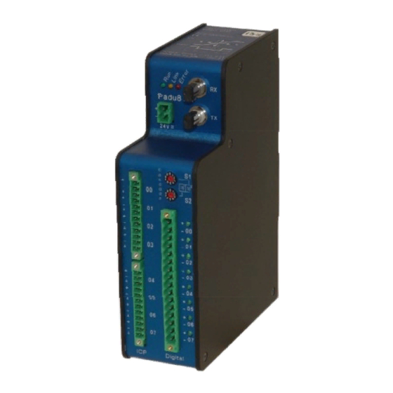
Page 12: Device View
Manual ibaPADU-8-ICP Device view Front View Description Top View Serial number and support information Status-LEDs (L1..L3) RX port (X11) 24 V DC Power Connector (X14) TX port (X10) Address Switches S1,S2 (1..96) ® inputs 00..03 (X1) binary inputs connector LEDs (L4..L11) binary inputs connector 00..07 (X5) -
Page 13: Power Supply Connection
Connect the TX port of the iba FOB-card to the RX port of the first ibaPADU-8-ICP device in the ring. Then, connect the TX port of this ibaPADU-8-ICP device to the RX port of the next ibaPADU- 8-ICP device in the ring. -
Page 14: Run, Link And Error Led Indicators
Manual ibaPADU-8-ICP Binary Terminal Block Pin Connections X5 Connector + channel 0 - channel 0 + channel 1 - channel 1 + channel 2 - channel 2 + channel 3 - channel 3 + channel 4 - channel 4 + channel 5 - channel 5 + channel 6 - channel 6... -
Page 15: Service Interface
Firmware may only be updated by iba! A 9-pin SUB-D port, found on the under side of the device, may be used to load new firmware for the device. New firmware is loaded via a V.24 interface. Please contact iba regarding loading new firmware. -
Page 16: System Integration
TX/RX port for transmission of control signals and reception of data from connected ibaPADU-8-ICP devices. All devices connected in each fiber-optic link must have unique addresses. The TX port on an individual iba- FOB interface must be con- nected to the RX port on the first ibaPADU-8-ICP in the fiber-optic ring. -
Page 17: Process Monitoring Topology Example
It is possible to couple other pro- cess signals using other input de- vices available from iba, in which case the corresponding interface must be available. For example, ibaPADU-8 devices... -
Page 18: Online Machine Condition Monitoring Topology
The use of the ibaBM-FOX-i-3o splitter in conjunction with ibaPADU-8-ICP is not sup- ported. Due to the bidirectional data transfer between ibaPADU-8-ICP and ibaFOB-card it is not possible to split the signals. If a multiplication of signals is required, please contact iba. Issue 1.7... -
Page 19: Programmable Settings Of The Device
ibaPADU-8-ICP Manual Programmable Settings of the Device Each ibaPADU-8-ICP is programmable. A single, common sampling rate for all chan- ® nels may be set. Each ICP input channel has a programmable gain and filter setting as well. Sampling Rate The sampling rate can be programmed via the ibaFOB interface in steps of 50 nano- seconds from 40 s (25 kHz) to 2 ms (500 Hz). -
Page 20: Low-Pass Filter
51000 Hz would be dampened 6 dB by the static low-pass filter. This signal would be noticeable for signal strengths above 20 dB. If a device for low-frequency applications should be required, iba can supply a variant of this device for sampling at 1 kHz or less, with a static low-pass filter. Please contact iba for further details. - Page 21 ibaPADU-8-ICP Manual These diagrams show the characteristics of the used programmable input filter. The filter itself causes a delay within the ibaPADU-8- ICP. This delay is named Group delay. At an edge frequency of 1 kHz this delay is approx. 80 s (see left.) Issue 1.7...
-
Page 22: Configuration
Manual ibaPADU-8-ICP Configuration ibaPADU-8-ICP is actually supported ibaLogic-V3, ibaScope and ibaPDA-V6 software. The following chapters describe example configurations in ibaLogic and ibaPDA. The settings in ibaScope correspond to the settings in ibaLogic, although the dialogs are slightly different. For setup of the device with ibaScope please refer to the ibaScope manual. -
Page 23: Hardware Settings
In ibaLogic there are corresponding dialogs. Basically, there are two operational modes: FOB-F and FOB-M. FOB-F is the mode of operation for usual data acquisition with the major part of iba de- vices such as PADU-8, -16, -32, ibaLink-SM-64-io, ibaLink-SM-128V-i-2o, ibaNet750- BM etc. - Page 24 Manual ibaPADU-8-ICP Then click on button <Configuration FOB I/O> to open the setup dialog for the FOB- card. Select the corresponding FOB-card in the tree on the left side. On the right side you see the settings of the selected card. Choose the line of the link which is connected to the ibaPADU-8-ICP and select FOB-M Mode in the fields for both “Receiver Format”...
-
Page 25: Checking The Communication With The Help Of Ibadiag
ibaPADU-8-ICP Manual 10.1.3 Checking the Communication with the Help of ibaDiag Start the diagnostics program over menu “Hardware - ibaDiag”. Select the FOB-card which is connected to the ibaPADU-8-ICP in the tree on the left side. On the right side you see a simplified representation of the card with the 7-segment- display for the card address of this type and the LEDs showing the status of every link. - Page 26 Manual ibaPADU-8-ICP The graphical representation of the ibaPADU-8-M device is not animated. The large table on the left side and the fields on the right side of the PADU picture show the settings of the Padu setup. If the FOB card is set to active mode by means of ibaDiag, which is only possible when ibaLogic is not running at this time, you may call the Padu setup dialog window by clicking on the button <Setup Padu M>.
-
Page 27: Input Resources Iba Fob-M/In
Status of data buffer (true, if number of values > buffer size) Quantity of available data (multiples of 10), if data available. Link status (true, if iba FOB M active and link available) True, if link status ok and ibaPADU-8-ICP activated. -
Page 28: Output Resources For Iba Fob-M (Fob-M/Out)
Please note, that the device will need a few seconds to adapt to the new parameters. After parameterization the device sends a continuous data stream to iba- Logic. Please note further that the change of parameters may affect the processing of other in- and output resources due to a halt of the drivers (lack of some cycles). -
Page 29: Control Of Ibapadu-8-Icp In Ibalogic Application Program
First, these are the values for gain and frequency for each channel to be used. The val- ues depend on the measurement arrangement and sensor types. For the supply of the other parameters iba developed a sample function block FOBM_Control which is available from iba on request. -
Page 30: Data Buffer Size
After installing ibaPDA and starting the ibaPDA client, select "Configure – I/O Man- ager…" in the main menu. 10.2.1 Configuring ibaPADU-8-ICP: 1. If several iba PCI cards are used in ibaPDA, set the board connected to ibaPADU-8-ICP to the interrupt mode "Master internal" and set the option "In use". Issue 1.7... - Page 31 2. Create the device module by one of the following actions: Press the icon "New configuration" When the device is connected correctly, the "autodetect" feature will find the iba- PADU-8-ICP and place module "Padu 8-ICP" on the connected FOB link. Alterna- tively right-click the link of the FOB-D or FOB-S card to which the ibaPADU-8-ICP is connected and select "Autodetect"...
- Page 32 Manual ibaPADU-8-ICP 3. Define the general properties Select the General Tab. Whenever you click to a property field, you will see its description in the comment area at the bottom of the tab. Define the properties: Basic: Locked: If true, the module can only be changed by authorized users.
- Page 33 AG recommends a multiple between 25 and 100. Device address: address 0..95, according to the rotary switch settings S1 and S2. Define the signal parameters.
- Page 34 Manual ibaPADU-8-ICP Filter: Choose a corner frequency for the digital low-pass filter from the dropdown menu. You can also display other signal properties in the grid with a right mouse click on the headline of the grid. In the same way, you can parameterize the digital signals. 5.
-
Page 35: Configuring Triggers
ibaPADU-8-ICP Manual 10.2.2 Configuring Triggers Alternative to the definition of single trigger events, ibaPDA supports the definition of multiple trigger events as a trigger pool. For using the trigger pool you must first define all possible trigger events. In the 2 step you must select the predefined events from the trigger pool to start and to stop storing the data. - Page 36 Manual ibaPADU-8-ICP The custom tab contains the regular expression builder. Finish the definition of one trigger event with <OK> Define further trigger events in the same way. Issue 1.7...
- Page 37 ibaPADU-8-ICP Manual Result: In the signal grid of the trigger module you see the overview of all defined trigger events. 2. Use the trigger events in the data store configuration The signals from the trigger modules can be used as triggers in the datastore. Each datastore has a start trigger pool and a stop trigger pool.
-
Page 38: Configuring The Data Store
Manual ibaPADU-8-ICP 10.2.3 Configuring the Data Store After finishing the configuration of the ibaPADU-8-ICP device, it is necessary to setup the data storage. For this, select "Configure – Data storage" in the main menu. Proceed as follows: 1. Activate and name the data store 2. -
Page 39: Configuring The Signal View
ibaPADU-8-ICP Manual 10.2.4 Configuring the Signal View After closing the I/O Manager and the Data storage configuration you are in the ibaPDA client main view. Mainly ibaPDA has three view types: The trend graph , the Scope view and the FFT view ... -
Page 40: Technical Data
Manual ibaPADU-8-ICP Technical data Order number iba 10.120100 Mechanical stability and DIN IEC 68-2-6; test parameters (all 3 axes) 1 g rms 90 Min @ 0..250 Hz / axis (all types) 2 g rms 90 Min @ 0..250 Hz / axis (all ibaPADU-8 types);... -
Page 41: Support And Contact
Koenigswarterstr. 44 90762 Fuerth Germany Phone: +49 911 97282-0 Fax: +49 911 97282-33 Email: iba@iba-ag.com Contact: Mr. Harald Opel Regional and Worldwide For contact data of your regional iba office or representative please refer to our web site www.iba-ag.com. Issue 1.7...
Need help?
Do you have a question about the PADU-8-ICP and is the answer not in the manual?
Questions and answers