Table of Contents
Advertisement
Quick Links
Instruction Manual
D103272X012
Fisherr LCP100 Local Control Panel
Contents
. . . . . . . . . . . . . . . . . . . . . . . . . . . . . . . . .
. . . . . . . . . . . . . . . . . . . . . . . . . . . . .
. . . . . . . . . . . . . . . . . . . . . . . . . . . . . . . . .
. . . . . . . . . . . . . . . . . . . . . . . . . . . . . . .
. . . . . . . . . . . . . . . . . . . . . . . . . . . . . . . . . .
Instructions for "Safe Use" and Installation
in Hazardous Areas
. . . . . . . . . . . . . . . . . . . . . . . . . . . . . . . . . .
. . . . . . . . . . . . . . . . . . . . . . . . . . . . .
. . . . . . . . . . . . . . . . . . . . . . . . . . . . . . . . . . . . . .
. . . . . . . . . . . . . . . . . . . . . . . .
. . . . . . . . . . . . . . . . . . . . . . . . . . . . . . . .
. . . . . . . . . . . . . . . . . . . . . . . . . . . .
. . . . . . . . . . . . . . . . . . . . . . . . . . . . . . .
. . . . . . . . . . . . . . . . . . . . . . . . . . . . . . . . . . .
. . . . . . . . . . . . . . . . . . . . . . . . . . . . .
Introduction
Scope of Manual
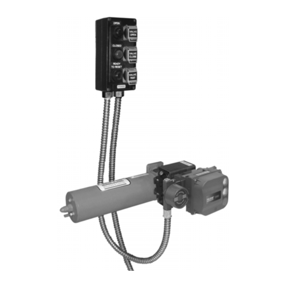
This instruction manual includes installation and maintenance information for the Fisher LCP100 local control panel
(figure 1). This device is used with Fisher FIELDVUEt instruments in Safety Instrumented Systems (SIS). Refer to the
DVC6200 SIS Digital Valve Controllers for Safety Instrumented System (SIS) Solutions instruction manual
(D103557X012) or the DVC6000 SIS Digital Valve Controllers for Safety Instrumented System (SIS) Solutions
instruction manual (D103230X012) for additional information.
Unless otherwise noted, the information in this instruction manual applies to both DVC6200 SIS and DVC6000 SIS
digital valve controllers. For simplicity, the DVC6200 SIS model name will be used throughout.
Do not install, operate, or maintain an LCP100 local control panel without being fully trained and qualified in valve,
actuator, and accessory installation, operation, and maintenance. To avoid personal injury or property damage, it is
important to carefully read, understand, and follow all of the contents of this manual, including all safety cautions and
warnings. If you have any questions about these instructions, contact your Emerson Process Management sales office.
www.Fisher.com
. . . . . . . . . . . . . . . . . . . . . . . .
. . . . . . . . . . . . . . . . . . . . . . . .
Figure 1. Fisher LCP100 Local Control Panel, with
FIELDVUE DVC6200 SIS Digital Valve Controller
1
and Bettis
t
Actuator
1
2
2
3
3
5
5
9
10
11
12
12
12
13
13
X0247
LCP100 Local Control Panel
August 2012
Advertisement
Table of Contents

Related Manuals for Emerson Fisher LCP100


Summary of Contents for Emerson Fisher LCP100
-
Page 1: Table Of Contents
Introduction Scope of Manual This instruction manual includes installation and maintenance information for the Fisher LCP100 local control panel (figure 1). This device is used with Fisher FIELDVUEt instruments in Safety Instrumented Systems (SIS). Refer to the DVC6200 SIS Digital Valve Controllers for Safety Instrumented System (SIS) Solutions instruction manual (D103557X012) or the DVC6000 SIS Digital Valve Controllers for Safety Instrumented System (SIS) Solutions instruction manual (D103230X012) for additional information. -
Page 2: Description
2.2 kg (4.9 lbs) 1. The pressure/temperature limits in this document and any applicable standard or code limitation should not be exceeded. 2. Contact your Emerson Process Management sales office for information on pending approvals. Description The LCP100 local control panel is used with the HARTr communicating DVC6200 SIS digital valve controller. This panel is used to manually open and close a safety shutdown valve. -
Page 3: Installation
Instruction Manual LCP100 Local Control Panel D103272X012 August 2012 Table 2. Electromagnetic Immunity Performance Criteria Port Phenomenon Basic Standard Test Level Performance Criteria $4 kV contact Electrostatic discharge (ESD) IEC 61000‐4‐2 $8 kV air Enclosure 80 to 1000 MHz @ 10V/m with Radiated EM field IEC 61000‐4‐3 1 kHz AM at 80%... - Page 4 Instruction Manual LCP100 Local Control Panel August 2012 D103272X012 If the LCP100 is connected to a DVC6200 SIS in a zone 1 explosion proof “d” environment, there must be a conduit seal installed between the DVC6200 SIS and the LCP100 in order to maintain the explosion proof integrity of the DVC6200 SIS.
-
Page 5: Mounting
Instruction Manual LCP100 Local Control Panel D103272X012 August 2012 Mounting Refer to figure 6 for dimensional information. The LCP100 local control panel has four (4) mounting holes for on‐site mounting of the device. The LCP100 must be installed so that the wiring connections are on the bottom to prevent accumulation of moisture inside the box. - Page 6 Instruction Manual LCP100 Local Control Panel August 2012 D103272X012 Figure 3. Wiring for 24 VDC External Power Configuration 24VDC LOGIC SOLVER OUTPUT 4‐20 mA (USER SUPPLIED) LCP100 SWITCH TO 24VDC POSITION AUX + 24VDC + CASE GROUND 24 VDC 24VDC * SOURCE AUX* (USER SUPPLIED) DVC6200 SIS TERMINAL BOX SHIELD NOT CONNECTED TO LCP100...
- Page 7 Instruction Manual LCP100 Local Control Panel D103272X012 August 2012 Figure 4. Wiring for Loop‐Powered Configuration; Logic Solver Wired to the Fisher LCP100 then the FIELDVUE DVC6200 SIS LCP100 LOOP SWITCH TO LOOP POSITION AUX + LOGIC SOLVER LOOP + CASE GROUND OUTPUT 8‐20 mA...
- Page 8 Instruction Manual LCP100 Local Control Panel August 2012 D103272X012 Figure 5. Wiring for Loop‐Powered Configuration; Logic Solver Wired to the FIELDVUE DVC60200 SIS then the Fisher LCP100 LCP100 SWITCH LOOP TO LOOP POSITION AUX CASE GROUND LOGIC SOLVER OUTPUT LOOP + 8‐20 mA...
-
Page 9: Pre-Setup Testing
Instruction Manual LCP100 Local Control Panel D103272X012 August 2012 Figure 6. Fisher LCP100 Local Control Panel Dimensions (7.6) (10.1) (3.7) (5.1) E1077‐1 (4.3) (INCH) Pre‐Setup Testing Before connecting the LCP100 to the process, conduct the following tests on the LCP100 connected to the DVC6200 SIS. -
Page 10: Setup
Instruction Manual LCP100 Local Control Panel August 2012 D103272X012 Emergency Demand through the Logic Solver 1. Reduce the current to the DVC6200 SIS to 4 mA (for de‐energize to trip operation). Note For a loop powered installation, a minimum current of 8 mA is required at the trip state / “Safety Demand” for proper functioning of the pushbuttons and lights. -
Page 11: Principle Of Operation
Select Yes. Principle of Operation The lights indicate the state of the valve as described in table 3. Table 3. Fisher LCP100 Light and Button Operation PRESS INDICATED BUTTON TO... WHAT THE LCP100 LIGHTS SHOW... -
Page 12: Maintenance
Parts Ordering When corresponding with your Emerson Process Management sales office about this equipment, mention the serial number found on the nameplate (key 10, figure 7) of the unit. When ordering replacement parts, state the complete 11‐character part number of each part required as found in the following parts list. -
Page 13: Parts List
Use only genuine Fisher replacement parts. Components that are not supplied by Emerson Process Management should not, under any circumstances, be used in any Fisher instrument. Use of components not supplied by Emerson Process Management may void your warranty and hazardous area approval, might adversely affect the performance of the instrument, and could cause personal injury and property damage. - Page 14 Instruction Manual LCP100 Local Control Panel August 2012 D103272X012 Figure 8. Key 9, Electronics Module GE39919‐A E1122...
- Page 15 Instruction Manual LCP100 Local Control Panel D103272X012 August 2012 Figure 9. Fisher LCP100 Connection to Explosion Proof “Ex d” FIELDVUE DVC6200 SIS; Loop Power ZONE 1 NON‐HAZARDOUS AREA CONDUIT SEAL LOGIC SOLVER DVC6200 SIS “Ex d” LCP100 “Ex em” LOOP POWERED—LOGIC SOLVER WIRED TO LCP100 FIRST ZONE 1 OR 2 NON‐HAZARDOUS AREA...
- Page 16 Responsibility for proper selection, use, and maintenance of any product remains solely with the purchaser and end user. Fisher, FIELDVUE, and Bettis are marks owned by one of the companies in the Emerson Process Management business unit of Emerson Electric Co. Emerson Process Management, Emerson, and the Emerson logo are trademarks and service marks of Emerson Electric Co.