Advertisement
PROPER USE GUIDELINES
Cumulative Trauma Disorders can result from the prolonged use of manually powered hand tools. Hand tools are intended for occasional use
and low volume applications. A wide selection of powered application equipment for extended-use, production operations is available.
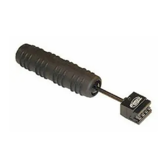
Wire
Inserter
Impact
Handle
1. INTRODUCTION
The 4-Pair Punch Down Tool 1725062-1 shown in
Figure 1 is used to insert and trim wire with the
110Connect XC Category 6 connecting blocks, wiring
blocks, and kits listed in Figure 1. The tool is also used
to install the connecting block to the index strip of the
wiring block. For more information on the installation
of connecting blocks and wiring blocks, refer to
instruction sheet 408-8823.
2. DESCRIPTION
The 4-Pair Punch Down Tool is equipped with an
impact mechanism to provide the force required to
insert and trim 4 pairs of wire at once. The tool is also
equipped with a reversible cut blade if the wires are
not to be trimmed.
© 2011 Tyco Electronics Corporation, a TE Connectivity Ltd. Company
All Rights Reserved
*Trademark
TE Connectivity, TE connectivity (logo), and TE (logo) are trademarks. Other logos, product and/or Company names may be trademarks of their respective owners.
4-Pair Punch Down Tool 1725062-1
TE PRODUCT
PART NUMBER
Cut Blade
1479245-1
Insert
1479246-1
1479247-1
1479248-1
1479249-1
Holder
1479250-1
1479251-1
1479252-1
1479253-1
1479254-1
1479255-1
1479256-1
1479257-1
1479258-1
1479259-1
1479260-1
1479261-1
1479262-1
1479263-1
1479264-1
Figure 1
TOOLING ASSISTANCE CENTER 1-800-722-1111
PRODUCT INFORMATION 1-800-522-6752
DESCRIPTION
CONNECTING BLOCK ASSEMBLY, 4 Pair
CONNECTING BLOCK ASSEMBLY, 5 Pair
WIRING BLOCK ASSEMBLY, 50 Pair with Mounting Legs
WIRING BLOCK ASSEMBLY, 100 Pair with Mounting Legs
WIRING BLOCK ASSEMBLY, 300 Pair with Mounting Legs
WIRING BLOCK ASSEMBLY, 50 Pair without Mounting Legs
WIRING BLOCK ASSEMBLY, 100 Pair without Mounting Legs
KIT, 50 Pair with Mounting Legs and 4 Pair Connecting Blocks
KIT, 50 Pair with Mounting Legs and 5 Pair Connecting Blocks
KIT, 100 Pair with Mounting Legs and 4 Pair Connecting Blocks
KIT, 100 Pair with Mounting Legs and 5 Pair Connecting Blocks
KIT, 300 Pair with Mounting Legs and 4 Pair Connecting Blocks
KIT, 300 Pair with Mounting Legs and 5 Pair Connecting Blocks
FRAME KIT, 300 Pair, with 4 Pair Connecting Blocks
FRAME KIT, 300 Pair, with 5 Pair Connecting Blocks
FRAME KIT, 900 Pair, with 4 Pair Connecting Blocks
FRAME KIT, 900 Pair, with 5 Pair Connecting Blocks
PANEL ASSEMBLY, Wiring Block, 100 Pair
PANEL ASSEMBLY, Wiring Block, 200 Pair
PANEL ASSEMBLY, Wiring Block, 400 Pair
The 4-Pair Punch Down Tool contains a sharp
DANGER
cutting blade. Improper use of tool may result in
damage to the tool or bodily injury.
STOP
3. CONNECTING BLOCK INSTALLATION PROCEDURE
Installation of the connecting block to the index strip
may be made easier through the use of the 4-Pair
Punch Down Tool. Refer to Figure 2.
4. INSERTING AND TRIMMING WIRE PROCEDURE
1. Hand lace each wire into the appropriate slot on
the connecting block or index strip.
2. Align the inserter blades on the tool with the
wires.
This controlled document is subject to change.
For latest revision and Regional Customer Service,
visit our website at www.te.com
Instruction Sheet
408-8852
22 AUG 11 Rev A
1 of 3
LOC B
Advertisement
Table of Contents

Related Manuals for TE Connectivity 1725062-1


Summary of Contents for TE Connectivity 1725062-1
- Page 1 PRODUCT INFORMATION 1-800-522-6752 For latest revision and Regional Customer Service, *Trademark visit our website at www.te.com LOC B TE Connectivity, TE connectivity (logo), and TE (logo) are trademarks. Other logos, product and/or Company names may be trademarks of their respective owners.
- Page 2 408-8852 5. SWITCHING CUT BLADE ORIENTATION Connecting Block 1. To switch cut blade orientation, pull the head off the main handle body. 2. Slide the cut blade insert and the wire inserter out of the holder. Punch Down Tool 3. Flip the cut blade insert. 4.
- Page 3 408-8852 ITEM NUMBER DESCRIPTION TE PART NUMBER QTY PER TOOL Handle Assembly 1725067-1 Cut Blade Insert 1725064-1 Wire Inserter 1725063-1 Figure 4 Rev A 3 of 3...
Need help?
Do you have a question about the 1725062-1 and is the answer not in the manual?
Questions and answers