Advertisement
Quick Links
Contents
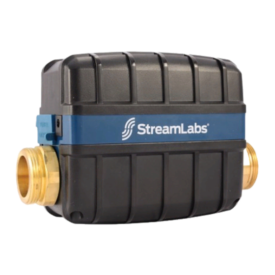
StreamLabs
Control
®
Temporary Bypass Flow Tube
Installation Guidelines
•
Failure to comply with all aspects of these instructions may result in unsafe
performance.
•
All installations must comply with relevant State, Provincial and Local
Authority requirements.
•
Control can be installed vertically or horizontally.
•
If installing a Control with SharkBite
appropriate grounding clamps and run a jumper wire across the unit.
•
Only use the provided StreamLabs DC Power Adapter.
•
The temporary bypass flow tube is for new construction or maintenance
applications of the Control.
•
Max pressure at max temperature: 200 psi at 105° F.
•
Control must be installed with correct flow direction as indicated on the
bottom of the unit.
Part 2: Setup & Installation
1. Locate your incoming cold water line.
The Control should be installed on the incoming water line after a shut-off valve and a
pressure regulating valve. The Control is not meant to be used as the main shut-off valve to
the house. If you do not have a main shut-off valve or pressure regulating valve, install prior
to installing the Control.
Ball Valve
PRV
Flow Direction
Not Monitored
Take note to install the Control prior to any pipe branches. Branches prior to the Control will
not be monitored or protected. At your installation location, you must have access to an
electrical outlet and a Wi-Fi signal. The Control comes with a DC power adapter with a 10
foot cord. Power adapters of additional lengths can be purchased from
StreamLabswater.com.
2. Check your Wi-Fi strength at your installation location. If there is an inadequate
Wi-Fi signal:
a) Choose another location closer to your wireless router.
b) Relocate your wireless router closer to the installation.
c) Purchase a wireless extender to improve Wi-Fi coverage.
3. Shut off your incoming cold water line.
4. Drain your plumbing system.
5. If installing a Control with SharkBite connections refer to the pipe cut out table
below. If installing a Control with FNPT connections, thread your adapters (not
included) onto the unions and measure the cutout length.
NPT or SharkBite Unions (2)
Gasket (4*)
3/4" and 1" come
with SharkBite
12V DC Power Adapter
Disconnect Clips**
*Two spare included, only one per fitting required for assembly
**1-1/4" Disconnect Clips can be purchased online
connections on copper pipe, use
®
Cold Water to Home
Monitored
Copyright© 2019 all rights reserved by StreamLabs
StreamLabs
Control
®
Installation Guide
Wi-Fi Indicator LED
Wi-Fi Reset Button
Open Button
Close Button
Part 1: Setup & Installation
1. Download the StreamLabs App.
2. Create an account or log in to an existing account.
3. Power your Control. The device should not be installed on pipe during initial
Wi-Fi pairing.
4. Follow the on-screen instructions in the app to setup and pair your device to
your wireless network.
5. Once Wi-Fi pairing is complete, unplug the Control, go to the installation
location and reference Part 2.
6. Cut and remove pipe section. Ensure the pipe is cut clean, square, and is free
from any dirt or debris.
7. Install unions onto the cut sections of pipe. (If using SharkBite unions, refer to
the side 2 for How to Install a SharkBite Push-to-Connect Fitting)
8. Place a gasket into each union.
9. Insert the Control between the unions. Thread the unions by hand onto each
side of the Control. Tighten the union nuts with a wrench.
Make sure the device is installed with the directional arrow (found on the bottom of the
unit) pointing toward the direction of water flow.
10. Turn the water back on and check the installation.
11. Open a downstream faucet to flush air from your lines.
12. Plug the DC Power Adapter to an outlet and run the cable to power the
Control. The device will automatically reconnect to Wi-Fi and the Wi-Fi icon
will turn green.
13. Test the Control by opening and closing the valve using the touch panel on the
device.
14. Return to the StreamLabs App to complete setup.
Pipe Cut Out Table
Pipe Size
SharkBite Pipe Cut Out Section
3/4 in.
8.5 in.
1 in.
10 in.
1-1/4 in.
10 in.
• Terms of Service • Privacy Policy
®
9V Battery
Access Cover
(temporary
alternate
power only)
Power
Adapter
Plugin
Advertisement

Subscribe to Our Youtube Channel
Related Manuals for StreamLabs Control

Summary of Contents for StreamLabs Control
- Page 1 The Control should be installed on the incoming water line after a shut-off valve and a pressure regulating valve. The Control is not meant to be used as the main shut-off valve to 7. Install unions onto the cut sections of pipe. (If using SharkBite unions, refer to the house.
- Page 2 Installing on a pipe other than the main line will not allow you to see all water usage in your home. The Control should only be installed indoors or in a covered, The Wi-Fi icon will indicate different connectivity status. See below for a guide on enclosed area where it is safe from excessive moisture, temperature fluctuations, how to interpret the Wi-Fi LED.
Need help?
Do you have a question about the Control and is the answer not in the manual?
Questions and answers