
Related Manuals for Hercules Fazua Futura


Summary of Contents for Hercules Fazua Futura
- Page 1 TRANSLATION OF THE ORIGINAL OPERATING INSTRUCTIONS IMPORTANT READ CAREFULLY BEFORE USE Pedelecs FUTURA Fold Carbon I-10S 21-Y-0001 MY21H05 - 1 • 1.0 • 30. November 2020...
-
Page 2: Table Of Contents
Contents Contents About these operating instructions 3.1.4 Electric drive system Manufacturer 3.1.5 Motor Language 3.1.6 Rechargeable battery Laws, standards and directives 3.1.7 Control panel For your information Charger 1.4.1 Warnings Proper use 1.4.2 Markups Improper use Nameplate Data privacy information Type number and model 3.5.1 Maximum permitted total weight... - Page 3 Contents Error messages 6.19.2 Preparing the bicycle so that it is Instruction and customer service ready to ride again Adjusting the pedelec 6.19.2.1 Folding out the frame 6.6.1 Adjusting the saddle 6.19.2.2 Folding out the pedal 6.6.1.1 Adjusting the saddle tilt 6.20 Parking the pedelec 6.6.1.2...
- Page 4 Contents Maintaining the stem Adjusting the gear shift 8.4.1 Cable-operated gear shift, single-cable 68 8.4.2 Cable-operated gear shift, dual-cable 8.4.3 Cable-operated twist grip, dual-cable Troubleshooting, fault clearance and repair Troubleshooting and fault clearance 9.1.1 The drive system or display do not start up 9.1.2 Assistance function errors...
- Page 5 About these operating instructions Thank you for your trust! Copyright © HERCULES GmbH HERCULES pedelecs are premium quality bicycles. You have made an excellent choice. Distribution or reproduction of these operating Your specialist dealer will provide you with instructions and utilisation or communication of...
-
Page 6: About These Operating Instructions
Manufacturer 1.4.1 Warnings The pedelec manufacturer is: Warnings indicate hazardous situations and HERCULES GMBH actions. You will find warnings in the operating Longericher Strasse 2 instructions: 50739 Köln, Germany Tel.: +49 4471 18735 0... -
Page 7: Markups
About these operating instructions 1.4.2 Markups Instructions for specialist dealers are highlighted in grey. They are indicated by a screwdriver symbol. Information for specialist dealers does not require non-professionals to take any action. You will find stylised forms of typeface in the operating instructions: Stylised form Italics... -
Page 8: Nameplate
Nameplate The nameplate is situated on the frame. You can You will find thirteen pieces of information on the see the exact position of the nameplate in Figure 2. nameplate. Hercules GmbH Longericher Str. 2 50739 Köln, Germany Typ: 21-17-1017... -
Page 9: Type Number And Model
About these operating instructions ype number and model These operating instructions are an integral part of pedelecs with the type numbers: Type no. Model Pedelec type 21-Y-0001 Futura Fold Carbon I-10 Folding bicycle Table 3: Type number, model and pedelec type Identifying the operating instructions The Identification number position is located on... -
Page 10: Safety
Safety Safety Residual risks 2.1.1 Risk of fire and explosion Metal objects may interconnect the battery's electrical terminals. The battery may self-ignite 2.1.1.1 Rechargeable battery and explode. The safety electronics may fail if the batteries are Never insert paper clips, screws, coins, keys damaged or faulty. -
Page 11: Water Penetration
Safety Toxic substances 2.1.2.2 Water penetration If water penetrates into the charger, there is a risk 2.2.1 Brake fluid of electric shock. Brake fluid may leak out after an accident or due Never charge the battery outdoors. to material fatigue. Brake fluid can be fatal if swallowed or inhaled. -
Page 12: Safety Markings And Safety Instructions
Safety Safety markings and safety What to do in an emergency instructions 2.7.1 Dangerous situation in road traffic The pedelec and battery nameplates contain In the event of any hazards or dangers in road these safety markings and safety instructions: traffic, apply the brakes on the pedelec until it comes to a halt. -
Page 13: Battery Vapours Emitted
Safety 2.7.4 Battery fire After swallowing Rinse out mouth with water. Never induce The safety electronics may fail if the battery is vomiting. Risk of aspiration! damaged or faulty. The residual voltage can cause a short circuit. The battery may self-ignite ... -
Page 14: Overview
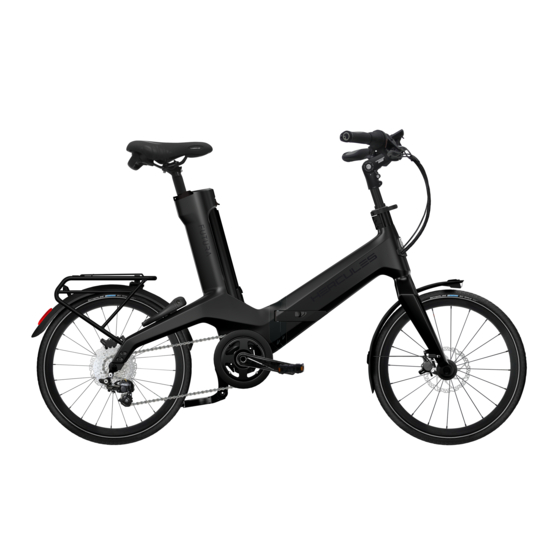
Overview Overview 13 14 15 16 Figure 2: Pedelec viewed from right: HERCULES Futura Fold Carbon I-10 used as example Front wheel Pannier rack Fork Rear light Front guard with headlight Rear guard Handlebars Rear wheel Stem Chain Frame Kickstand... -
Page 15: Description
About these operating instructions Description 3.1.2 Suspension 3.1.1 Wheel 3.1.2.1 Suspension fork Unlike a rigid fork, a suspension fork has two functions which improve floor contact and comfort: suspension and damping. The suspension prevents an impact, such as one caused by a stone lying in the pedelec's path, from being channelled directly into the rider's body via the fork. - Page 16 About these operating instructions Negative deflection The pedelec rebounds at a controlled speed if it is optimally adjusted. The wheel stays in contact Sag is the percentage of total deflection that is with the ground when passing over bumps compressed by the rider's weight, including (blue line).
-
Page 17: Steel Suspension Fork
About these operating instructions 3.1.3 Brake system 3.1.2.2 Steel suspension fork The stem and handlebars are fastened to the fork The pedelec features a hydraulic brake system. steerer. The wheel is fastened to the axle. The brake fluid is in a closed hose system. If the rider pushes the brake lever, the brake fluid activates the brake on the wheel. -
Page 18: Electric Drive System
Overview 3.1.4 Electric drive system 3.1.5 Motor The pedelec is driven by muscle power applied to the chain drive. The force which is applied by pedalling in the direction of travel drives the front chain wheel. The chain transmits the force onto the rear chain wheel and then onto the rear wheel. -
Page 19: Rechargeable Battery
Overview 3.1.6 Rechargeable battery When the battery is switched on, the battery level indicator shows the start animation. The LEDs then briefly indicate the charge level of the battery. If the battery is switched on, the charge level can be queried by briefly pressing the On-Off button. 3.1.7 Control panel Figure 13: Rechargeable battery, view of charging port... -
Page 20: Charger
Overview Charger The lithium ion battery has an internal electronic protection circuit, It is matched to the charger. You must therefore only use the supplied charger to charge the pedelec. Nominal input voltage 100 ... 240 V AC Frequency 50 ... 60 Hz Output voltage 42 V DC Charging current... -
Page 21: Proper Use
Overview Proper use The pedelec must only be used in perfect, fully actions in these operating instructions met. functional condition. National requirements may Approved accessories can be installed by apply to the pedelec which the standard specialist staff. equipment may not meet. For riding on public The rechargeable batteries are designed to roads, some special regulations apply in relation supply power to the pedelec motor only and must... -
Page 22: Improper Use
Overview Improper use Failure to adhere to the proper use poses a risk of • lending the pedelec to untrained riders • carrying other people personal injury and material damage. It is • riding with excessive baggage prohibited to use the pedelec in the following •... -
Page 23: Technical Data
Overview Technical data Rechargeable battery Type Lithium ion battery 3.6.1 Pedelec Nominal voltage 36 V Transportation temperature -15 ... +60 °C Nominal capacity 7 Ah Storage temperature -15 ... +60 °C Power 252 Wh Discharging temperature -15 ... +60 °C Operating temperature -20 ... -
Page 24: Emissions
Overview 3.6.2 Emissions A-weighted emission sound pressure < 70 dB(A) level Total vibration level for the hands and < 2.5 m/s² arms Highest effective value of weighted < 0.5 m/s² acceleration for the entire body Table 17: Emissions from the pedelec* *The safety requirements as per Electromagnetic Compatibility Directive 2014/30/EU have been met. -
Page 25: Description Of Controls And Screens
Overview Description of controls and 3.7.3 Control panel indicators screens 3.7.4 Control panel 3.7.1 Handlebars Figure 16: Detailed view of pedelec from rider position, example Figure 18: Overview of the structure and operating elements Rear brake lever Front brake lever Designation Control panel Display bar... -
Page 26: Level Of Assistance
Overview Status screen Remaining range The status screen indicates a status change or an Precise information about the range of your existing fault. The status indicator does not light system is not possible before or during an up if no fault is detected. excursion. -
Page 27: Environmental Requirements
Overview Environmental requirements You can be ride the pedelec within a temperature Temperatures under -10 °C and over +40 °C must range between 5 °C and 35 °C. The electric drive be avoided. system is limited in its performance outside this You must also keep within the following temperature range. - Page 28 Overview The pedelec is unsuitable for the following areas of use: Child's bicycles/ City and trekking Area of use bicycles for young Mountain bikes Racing bicycle Cargo bike Folding bicycle bicycles adults Never drive off-road Never drive off-road Never drive off-road Never drive off-road Never drive off-road or perform jumps.
-
Page 29: Transporting And Storing
Transporting and storing Transporting and storing Physical transport characteristics Weight and dimensions during transportation t.b.a. t.b.a. t.b.a. 21-Y-0001 t.b.a. t.b.a. t.b.a. t.b.a. t.b.a. t.b.a. Vehicle weight without battery. The vehicle’s total weight depends on the battery used 4.1.1 Designated handles/lifting points The box does not have any handles. -
Page 30: Transportation
Transporting and storing Transportation 4.2.2 Transporting the pedelec Bicycle rack systems which use the handlebars or CAUTION frame to hold the pedelec in an upside-down position exert inadmissible forces on its Crash caused by unintentional activation components during transportation. This can cause There is a risk of injury if the drive system is the supporting parts to break. -
Page 31: Storing
Transporting and storing Storing 4.3.1.1 Preparing a break in operation Remove the rechargeable battery from the Store pedelec, battery and charger in a clean, pedelec. dry place where they are protected from sunlight. Do not store outdoors to ensure a Charge battery to around 30%–60%. -
Page 32: Assembly
Assembly Assembly Unpacking The packaging material consists mainly of cardboard and plastic film. WARNING The packaging has to be disposed of in Risk of eye injury accordance with the regulations of the Problems may arise if the settings are not made authorities. -
Page 33: Commissioning
Assembly Commissioning 5.4.1.2 Firm hold 1 Place your entire body weight on the CAUTION handlebars with the quick release lever closed to check that the stem is firmly in place. Burns from hot drive The handlebars shaft must not move The drive cooler can become extremely hot downwards in the fork steerer. -
Page 34: Operation
Operation Operation Risks and hazards CAUTION WARNING Crash caused by loose clothing Injuries and death caused by other road users Shoe laces, scarves and other loose items may become entangled in the spokes on the wheels Other road users, trucks, cars or pedestrians often and on the chain drive. -
Page 35: Personal Protective Equipment
Operation Notice CAUTION Moisture penetrating at low temperatures may Crash caused by poor road conditions impair individual functions due to the open structural design. Loose objects, such as branches and twigs, may become caught in the wheels and cause a crash ... - Page 36 Operation Weight Minimise the total weight of pedelec and baggage. Stopping and starting Ride long distances at a constant speed. Avoid stopping and starting frequently. Gear shift Use a low gear and a low level of assistance on hills and when setting off.
-
Page 37: Error Messages
Operation Error messages The status screen indicates a status change or an existing fault. The status indicator does not light up if no fault is detected. The different colours of the status screen have the following meaning: Colour Meaning The status screen flashes green briefly after the drive pack has been successfully installed into the Green pedelec. -
Page 38: Instruction And Customer Service
Operation Instruction and customer service Adjust the saddle tilt to horizontal. Your supplying specialist dealer will provide customer service. Contact details can be found on the pedelec pass for these operating instructions. The specialist dealer will explain all the pedelec functions to you in person, this being when the specialist dealer hands over the pedelec at the latest. -
Page 39: Adjusting The Seat Height With
Operation 6.6.1.3 Adjusting the seat height with 6.6.1.4 Height-adjustable seat post quick release Only applies to pedelecs with this equipment 1 Open the quick release on the seat post to Preparing change the seat height (1). To do so, push the clamping lever away from the seat post (3). -
Page 40: Adjusting The Seat Position
Operation 6.6.1.5 Adjusting the seat position 6.6.2 Adjusting the handlebars The saddle can be shifted on the saddle frame. CAUTION The right horizontal position ensures an optimal leverage position for legs. This prevents knee Crash caused by incorrectly set clamping pain and painful incorrect pelvis positions. -
Page 41: Adjusting The Quick Release Clamping
Operation 6.6.5 Retracting the brake linings Disc brakes require wearing-in time. The braking force increases over time. You therefore need to be aware that the braking force may increase during the wearing-in period. The same happens after brake pads or discs are replaced. 1 Accelerate pedelec to about 25 km/h. -
Page 42: Accessories
Operation Accessories We recommend a parking stand into which either the front wheel or rear wheel can be inserted securely for pedelecs which do not have a kickstand. The following accessories are recommended: Description Article number Protective cover for electrical 080-41000 ff components Panniers,... -
Page 43: Check List Before Each Ride
Operation Check list before each ride Check the pedelec before each ride. Take the pedelec out of service if you spot any anomalies. Check that the pedelec is complete. Check the battery is firmly in place. Check that the lighting, reflector and brake, for instance, ... -
Page 44: Raising The Kickstand
Operation Raising the kickstand Distribute the baggage as evenly as possible between the left- and right-hand side. Use your foot to raise the kickstand completely We recommend the use of panniers and before setting off. baggage baskets. 6.10 Using the pannier rack The maximum load bearing capacity is indicated... -
Page 45: Charger
About these operating instructions 6.12 Charger 6.12.1 Connecting the charger to the mains Connect the mains plug on the connecting cable to the power jack on the charger. Connect the mains plug (country-specific) on the connecting cable to the power supply. Nominal input voltage 100 ... -
Page 46: Inserting The Battery Into The Drive Unit
About these operating instructions Charging begins as soon as the charger plug is 6.13.3 Removing the battery from the drive connected to the charging socket on the unit connected battery. The charge level is displayed by the battery level indicator on the battery. -
Page 47: Removing The Drive Unit From The
About these operating instructions The drive unit is now unlocked. Lock the drive unit to protect it against theft. -90° Figure 36: Removing the drive unit from the pedelec Hold the drive unit firmly with one hand. Figure 34: Locking the drive unit ... -
Page 48: Electric Drive System
Operation 6.15 Electric drive system 6.15.3 Drive system standstill The pedelec shuts down 6.15.1 Switching on the electric drive system If the pedelec has not been moved for 10 hours and no button has been pressed on the control CAUTION panel or ... -
Page 49: Control Panel
Operation 6.16 Control panel 6.16.2 Selecting the level of assistance Press the top or bottom button on the control Notice panel. The following levels of assistance are Do not use the display as a handle. You may possible: irreparably damage the display if you use it to Level of assistance lift the pedelec. -
Page 50: Brake
Operation 6.17 Brake WARNING Crash caused by brake failure If the brakes are applied continuously for a long time (e.g. while riding downhill for a long time), the fluid in the brake system may heat up. This may create a vapour bubble. Any air bubbles or water contained in the brake system may expand due to heat. -
Page 51: Gear Shift
Operation 6.18 Gear shift The selection of the appropriate gear is a prerequisite for a physically comfortable ride and making sure that the electric drive system functions properly. The ideal pedalling frequency is between 70 and 80 revolutions per minute. ... -
Page 52: Folding
Operation 6.19 Folding 6.19.1.2 Folding up the stem, version I Only applies to pedelecs with this equipment Notice 1 Open the clamping lever on the stem quick Never crush or bend cables, electric cables or release. brake cables when folding. 2 Pull the locking lever on the stem upwards and simultaneously pivot it 90°... -
Page 53: Pushing In The Seat Post
Operation 6.19.2 Preparing the bicycle so that it is 6.19.1.4 Pushing in the seat post ready to ride again 1 Open the clamping lever for the quick release on the seat post. The bicycle is prepared so that it is ready to ride again in eight steps. -
Page 54: Folding Out The Pedal
Operation 6.19.2.2 Folding out the pedal Push the pedal against the pedal crank with the foot from the front. Figure 45: Pushing the pedal against the pedal crank (1) Use the foot to fold the pedal up or down. Figure 46: Folding up the pedal MY21H05-2_1.0_30.11.2020... -
Page 55: Parking The Pedelec
Operation 6.20 Parking the pedelec Notice Heat or direct sunlight can cause the tyre pressure to increase above the permitted maximum pressure. This can destroy the tyres. Never park the pedelec in the sun. On hot days, regularly check the tyre pressure and adjust it as necessary. -
Page 56: Cleaning And Servicing
Cleaning and servicing Cleaning and servicing Cleaning check list WARNING Clean the pedals after each ride Crash caused by brake failure Suspension fork after each ride Oil or lubricant on the brake disc in a disc brake Cleaning the battery once a month or on the rim of a rim brake can cause the brake... -
Page 57: Cleaning After Each Ride
Cleaning and servicing Cleaning after each ride Notice Water may enter the inside of the bearings if you Required tools and cleaning agents: use a steam jet. This dilutes the lubricant inside, • Cloth the friction increases and, as a result, the •... -
Page 58: Basic Cleaning
Cleaning and servicing Basic cleaning 7.2.4 Cleaning the drive elements 1 Spray the cassette, the chain wheels and the Required tools and cleaning agents: front derailleur with a degreasing agent. • Cloths 2 Clean coarse dirt with a brush after soaking for •... -
Page 59: Cleaning The Display
Cleaning and servicing 7.2.9 Cleaning the brake Notice Never clean the battery with solvents, such as WARNING oil, thinners, alcohol or corrosion protection, or with cleaning agents. Brake failure due to water penetration The brake seals are unable to withstand high ... -
Page 60: Servicing The Frame
Cleaning and servicing 7.3.1 Servicing the frame Maintenance Dry the frame. The following maintenance measures must be performed on a regular basis. Spray with care oil. 7.4.1 Wheel Clean off the care oil again after a short time. 7.3.2 Servicing the stem WARNING... -
Page 61: Checking And Adjusting The Tyre Pressure
Cleaning and servicing 7.4.1.3 Checking and adjusting the tyre Presta valve pressure Only applies to pedelecs with this equipment It is recommendable to use Notice a bicycle pump with a If the tyre pressure is too low in the tyre, the tyre pressure gauge. -
Page 62: Brake System
Cleaning and servicing 7.4.4 Checking the pressure point 6 Screw the rim nut (1) gently against the rim with the tips of your fingers. Pull brake lever and hold repeatedly several 7.4.2 Brake system times. If you are unable to clearly detect the pressure CAUTION point and it changes, the brake needs to be bled. -
Page 63: Checking The Usb Port
Cleaning and servicing 7.4.9 Checking the USB port Regularly check the position of the cover on the USB port and adjust it as necessary. 7.4.10 Checking the chain tension Notice Excessive chain tension increases wear. If the chain tension is too low, there is a risk that the chain will slip off the chain wheels. -
Page 64: Maintenance
About these operating instructions Maintenance CAUTION Hazard for the environment due to toxic WARNING substances Injury due to damaged brakes The brake system contains toxic and environmen- tally harmful oils and lubricants. Such fluids will con- Special tools and specialist knowledge are taminate if they enter the sewers or groundwater. -
Page 65: Suspension System
About these operating instructions The specialist dealer will fully inspect the WARNING interior and exterior of the rear frame damper, overhaul the rear frame damper, replace all air Injury due to explosion seals on air forks, overhaul the air suspension, change the oil and replace the dust wipers. -
Page 66: Suspension Fork
About these operating instructions 8.1.2 Suspension fork WARNING Only applies to pedelecs with this equipment Injury due to explosion Maintenance intervals The air chamber is pressurised. If the air system is Suntour suspension fork serviced in a faulty suspension fork, it can explode and cause serious injury. -
Page 67: Suspension Seat Post
About these operating instructions 8.1.3 Suspension seat post Axle with quick release Only applies to pedelecs with this equipment CAUTION Maintenance intervals Crash caused by unfastened quick release by.schulz seat post Check all screws for correct tightening A faulty or incorrectly installed quick release may After 250 km and ... -
Page 68: Checking The Quick Release
About these operating instructions 8.2.1 Checking the quick release Adjusting the gear shift Check the position and clamping force of the If you cannot select the gears effortlessly, you will quick release lever. The quick release lever need to adjust the setting for the shift cable must be flush with the lower housing. -
Page 69: Cable-Operated Gear Shift, Dual-Cable
About these operating instructions 8.4.2 Cable-operated gear shift, dual- 8.4.3 Cable-operated twist grip, dual- cable cable Only applies to pedelecs with this equipment Only applies to pedelecs with this equipment For a smooth gear shift, set the adjusting For a smooth gear shift, set the adjusting sleeves underneath the chain stay on the sleeves on the shifter housing. -
Page 70: Troubleshooting, Fault Clearance And Repair
Troubleshooting, fault clearance and repair Troubleshooting, fault clearance and repair Troubleshooting and fault clearance The components of the drive system are checked constantly and automatically. If an error is detected, an error message appears on the display. The drive may be shut off automatically, depending on the type of error. -
Page 71: Assistance Function Errors
Troubleshooting, fault clearance and repair 9.1.2 Assistance function errors Symptom Cause Remedy Check battery is charged. Is the battery charged sufficiently? Recharge the battery if it is almost flat. Are you riding up long inclines in Switch off the drive system. summer weather or have you been Wait a moment and then check again. -
Page 72: Battery Error
Troubleshooting, fault clearance and repair 9.1.3 Battery error Symptom Cause Remedy The battery discharges The battery may be at the end of its Replace the battery with a new one. quickly. useful life. Pull out the charger mains plug and reconnect it again. Try charging again. -
Page 73: Display Errors
Troubleshooting, fault clearance and repair Symptom Cause Remedy Move away from the battery immediately. There is an unusual smell Contact the fire service immediately. Observe all the safety instructions in Section 2 Safety. Fumes are emitted from Move away from the battery immediately. the battery. -
Page 74: Repair
Troubleshooting, fault clearance and repair Symptom Cause Remedy This occurs when a warning or an error is shown on the Three beeps are A fault or warning has occurred. display screen. Follow the instructions for the code indicated sounded. on screen in Section 6.2 System Messages. -
Page 75: Recycling And Disposal
Recycling and disposal Recycling and disposal This device is marked according to the European Directive 2012/19/EU on waste electrical and electronic equipment – WEEE and the European Directive 2006/66/EC on accumulators. The directive provides the framework for the return and recycling of used devices across the EU. -
Page 76: Documents
Documents Documents 11.1 Parts list 11.1.1 Futura Fold Carbon I-10 21-Y-0001 Component Fork Carbon, rigid, 1.5" Handlebars Trekking AL, 31.8 mm, 15° backsweep Stem AL, height-adjustable, 90 mm, with "All Up" height adjustment, 150 mm Saddle Selle Royal LookIn Relaxed Seat post Kalloy SP-DC1, AL, 350 mm, Ø30.9 mm Crank set... -
Page 77: Assembly Report
Documents 11.2 Assembly report Date: Frame number: Components Description Criteria Measures if rejected Accept- Assembly/inspection Tests Rejection ance Front wheel Assembly O.K. Loose Adjust quick release Kickstand Check mount fastening Functional check O.K. Loose Retighten screws Tyre pressure too low/ Tyres Tyre pressure check O.K. - Page 78 Documents Components Description Criteria Measures if rejected Drive/gear shift Chain/cassette/ Refasten if necessary or replace Check for damage O.K. Damage pinion/chainring as specified in parts list Chain guard/spoke Check for damage O.K. Damage Replace as specified in parts list guard Bottom bracket axle/ Check mount fastening O.K.
-
Page 79: Maintenance Instructions
Documents 11.3 Maintenance instructions Diagnosis and documentation of current status Date: Frame number: Components Frequency Description Criteria Measures if rejected Inspection Tests Maintenance Accept- Rejection ance Front wheel 6 months Assembly O.K. Loose Adjust quick release Kickstand 6 months Check mount fastening Functional check O.K. - Page 80 Documents Components Frequency Description Criteria Measures if rejected Inspection Tests Maintenance Accept- Rejection ance Light system First examination O.K. Error message Contact battery Rechargeable 6 months manufacturer; take out of battery service, new battery Connections, correct O.K. Cable defective, New cabling Light cabling 6 months wiring...
- Page 81 Documents Technical inspection, checking safety, test ride Components Description Criteria Measures if rejected Assembly/inspection Tests Accept- Rejection ance No full braking; braking Locate defective part in brake Brake system 6 months Functional check O.K. distance too long system and correct Gear shift under Problems when shifting 6 months...
- Page 82 Documents Notes MY21H05-2_1.0_30.11.2020...
-
Page 83: Glossary
Glossary Glossary Electrically power assisted cycle, pedelec Source: EN 15194:2017: electrically power Brake lever assisted cycle, equipped with pedals and an auxiliary electric motor, which cannot be propelled Source: EN 15194:2017: lever used to apply the exclusively by means of the auxiliary electric brake. - Page 84 Glossary Maximum saddle height Quick-release device, quick release Source: EN 15194:2017: vertical distance from Source: EN 15194:2017: lever actuated the ground to the point where the top of the seat mechanism that connects, retains or secures a surface is intersected by the seat-post axis, wheel or any other component.
-
Page 85: Abbreviations
Glossary Weight of ready-to-ride bicycle Source: ZEG: the indicated weight for a ready-to- ride bicycle refers to the weight of a pedelec at the time of sale. The weight of each additional accessory must be added to this weight. Wheel Source: EN 15194:2017: assembly or combination of hub, spokes or disc, and rim, but excluding tyre assembly. -
Page 86: Appendix
The following other technical standards have been applied: • EN 11243:2016: Cycles – Pannier racks for bicycles – Requirements and test methods Cologne, 16.11.2020 ………………………………………………………………………………………………… Georg Honkomp, CEO HERCULES GmbH * Community member who is authorised to compile the technical documentation MY21H05-2_1.0_30.11.2020... -
Page 87: Keyword Index
Keyword index Keyword index Alternative equipment, 85 Fork, Saddle, 14, 44 Articulated shaft, – care, 60 - changing the saddle tilt, 38 – care 60 - cleaning, 57 - changing the seat length, 40 Frame, 14 - cleaning, 59 – care, 60 - determining the saddle height, 38, Basic cleaning 58 - cleaning, 58...
Need help?
Do you have a question about the Fazua Futura and is the answer not in the manual?
Questions and answers