Table of Contents
Advertisement
Quick Links
Advertisement
Table of Contents

Related Manuals for dallmeier Mountera Box with PSU


Summary of Contents for dallmeier Mountera Box with PSU
- Page 1 Mountera® Box COMMISSIONING 007806 | REV. 1.0.1 | 2020-01-24...
- Page 2 All trademarks identified by ® are registered trademarks of Dallmeier. Third-party trademarks are named for information purposes only. Dallmeier respects the intellectual property of third parties and always attempts to ensure the complete identification of third-party trademarks and indication of the respective holder of rights.
-
Page 3: Table Of Contents
Appropriate Use 7 Requirements Ambient Conditions Earthing/Grounding Power Supply 8 Maintenance, Inspection and Cleaning 9 Mounting, Connection and Commissioning 10 Parts Description 11 Technical Product Specification (Basic Data) 12 Dimensions COMMISSIONING – Mountera® Box | REV. 1.0.1 | © 2020 Dallmeier... -
Page 4: Validity
Keep all documents in legible condition and in a suitable location for future reference. Regularly check the website www.dallmeier.com for the latest product documentation updates. COMMISSIONING – Mountera® Box | REV. 1.0.1 | © 2020 Dallmeier... -
Page 5: This Document
VideoIP server software SMAVIA Recording Server. The target audience of the document is trained system integrators (installa- tion contractors of video security/surveillance systems). COMMISSIONING – Mountera® Box | REV. 1.0.1 | © 2020 Dallmeier... -
Page 6: Typographical Conventions
NOTICE addresses practices not related to physical injury and indicates measures to prevent device and/or property damage due to improper installation, assembly, wiring, operation, configuration or maintenance of the device. COMMISSIONING – Mountera® Box | REV. 1.0.1 | © 2020 Dallmeier... - Page 7 (menu items, buttons, etc.). Paragraphs in italics provide information on basic principles, special features and efficient procedure as well as general recommendations. COMMISSIONING – Mountera® Box | REV. 1.0.1 | © 2020 Dallmeier...
-
Page 8: Approvals/Certifications
Operation of this equipment in a residential area is likely to cause harmful interference in which case the user will be required to correct the interfer- ence at his own expense. COMMISSIONING – Mountera® Box | REV. 1.0.1 | © 2020 Dallmeier... -
Page 9: Safety Instructions
Dallmeier. Inappropriate modifications (e.g. unapproved paintwork or housing add-ons) may cause malfunctions, damage and data loss and may result in the loss of warranty. COMMISSIONING – Mountera® Box | REV. 1.0.1 | © 2020 Dallmeier... - Page 10 DIN, VDE and ISO standards and which provide for a standard-compliant earthing/grounding and a correct equipotential bonding of electrical and electronic devices, are mandatory and must be fulfilled by all means. COMMISSIONING – Mountera® Box | REV. 1.0.1 | © 2020 Dallmeier...
- Page 11 Interrupt the mains voltage to the device (e.g. switch off the correspond- ing circuit breaker) and remove all connected peripherals. Return the device to the sales partner responsible for your area. COMMISSIONING – Mountera® Box | REV. 1.0.1 | © 2020 Dallmeier...
-
Page 12: General Notes
The device should only be shipped in the original packaging. If the original packaging is no longer available, ensure that the used packag- ing sufficiently protects the device against damage, moisture, heat and cold. COMMISSIONING – Mountera® Box | REV. 1.0.1 | © 2020 Dallmeier... -
Page 13: Warranty
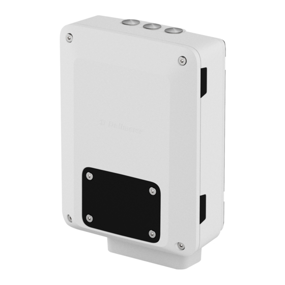
Mountera® Box with PSU with a SMAVIA Recording Server Appliance. The fanless and energy-efficient server hardware offers passive cooling and allows decentralized recording of high-resolution video streams on the built-in SSD memory directly at the installation site. COMMISSIONING – Mountera® Box | REV. 1.0.1 | © 2020 Dallmeier... -
Page 14: Requirements
Use of the device under unfavorable ambient conditions may shorten its lifetime and may cause malfunction or damage to the device. ➡ Only install and operate the device under favorable ambient conditions. COMMISSIONING – Mountera® Box | REV. 1.0.1 | © 2020 Dallmeier... -
Page 15: Earthing/Grounding
(EMI). ➡ Observe the locally applicable regulations (regional and country-specific legal requirements and standards) regarding the required minimum cross-sections for the earthing/grounding cables used. COMMISSIONING – Mountera® Box | REV. 1.0.1 | © 2020 Dallmeier... -
Page 16: Power Supply
(protection against dangerous contact voltages). ➡ Observe the locally applicable regulations (regional and country-specific legal requirements and standards) regarding the required minimum cross-sections for the conductors of the power supply line (mains cable). COMMISSIONING – Mountera® Box | REV. 1.0.1 | © 2020 Dallmeier... -
Page 17: Maintenance, Inspection And Cleaning
➡ Clean the outside of the housing with a clean, soft and dry cloth. • Do not use detergents. • Do not use microfiber cleaning cloths. • Avoid excessive rubbing. COMMISSIONING – Mountera® Box | REV. 1.0.1 | © 2020 Dallmeier... -
Page 18: Mounting, Connection And Commissioning
In addition, strictly observe the locally applicable regulations (regional and country-specific legal requirements and standards) regarding the mandatory measures for securing your Panomera® system or camera against falling while in operation or during maintenance. COMMISSIONING – Mountera® Box | REV. 1.0.1 | © 2020 Dallmeier... - Page 19 • Crimping tool for used cable lugs • Small slotted screwdriver or similar tool for lifting the strain relief clamp out of the “Power In” cable strain relief plate COMMISSIONING – Mountera® Box | REV. 1.0.1 | © 2020 Dallmeier...
- Page 20 ⌀ 8 mm × L 100 mm. ➡ Mark the drill hole locations on the ceiling/wall (use the supplied drilling template if necessary). ➡ At the marked locations, drill holes fitting the used mounting screws/anchors. COMMISSIONING – Mountera® Box | REV. 1.0.1 | © 2020 Dallmeier...
- Page 21 ➡ Remove the paper backing from the self-adhesive foam pad. ➡ Adhere the foam pad onto the rear side of the Mountera® Box while ensuring that the foam pad is aligned as illustrated in Fig. 2. COMMISSIONING – Mountera® Box | REV. 1.0.1 | © 2020 Dallmeier...
- Page 22 The foam pad compensates for small gaps between the device and the supporting structure that may result from manufacturing tolerances of the device or uneven/textured surfaces of the ceiling/wall. COMMISSIONING – Mountera® Box | REV. 1.0.1 | © 2020 Dallmeier...
- Page 23 ❸ Fig. 4 ➡ Loosen the 4 screws of the front lid in counterclockwise direction using the supplied hexagon socket screw key (size 5). COMMISSIONING – Mountera® Box | REV. 1.0.1 | © 2020 Dallmeier...
- Page 24 Fig. 5 ➡ Remove the front lid from the front cover. ➡ Place the front lid back into the original packaging of the device for later reuse. COMMISSIONING – Mountera® Box | REV. 1.0.1 | © 2020 Dallmeier...
- Page 25 ❹ Fig. 6 ➡ Loosen the 4 screws of the front cover in counterclockwise direction using the supplied hexagon socket screw key (size 5). COMMISSIONING – Mountera® Box | REV. 1.0.1 | © 2020 Dallmeier...
- Page 26 Fig. 7 ➡ Open the front cover. COMMISSIONING – Mountera® Box | REV. 1.0.1 | © 2020 Dallmeier...
- Page 27 18. ➡ Mount the housing body of the Mountera® Box on the ceiling/wall using the 4 supplied plastic frame anchors with hexagon head screw (push-through installation). COMMISSIONING – Mountera® Box | REV. 1.0.1 | © 2020 Dallmeier...
- Page 28 Fig. 9 ➡ Carefully drive the 4 plastic frame anchors with hexagon head screw into the ceiling/wall using a rubber mallet as illustrated in Fig. 9. COMMISSIONING – Mountera® Box | REV. 1.0.1 | © 2020 Dallmeier...
- Page 29 ➡ Tighten the 4 mounting screws in clockwise direction using a ratch- eting wrench handle with extension and 6-point socket (drive style: external hex, size: 10 mm) until the Mountera® Box is securely fixed on the ceiling/wall. COMMISSIONING – Mountera® Box | REV. 1.0.1 | © 2020 Dallmeier...
- Page 30 ❻ Fig. 11 ➡ Unscrew the polyamide locknut of the factory pre-assembled cable entry plate in counterclockwise direction. ➡ Remove the sealing plate with threaded ring COMMISSIONING – Mountera® Box | REV. 1.0.1 | © 2020 Dallmeier...
- Page 31 Fig. 12: Mountera® Cable Set C (optionally available) ➡ Unscrew the polyamide locknut counterclockwise from the sealing plate of the optionally available Mountera® Cable Set C. ➡ Remove the locknut. COMMISSIONING – Mountera® Box | REV. 1.0.1 | © 2020 Dallmeier...
- Page 32 ➡ Feed the Mountera® Cable Set C cables through the circular opening in the front cover as illustrated in Fig. 13. ➡ Insert the sealing plate with threaded ring into the circular opening. COMMISSIONING – Mountera® Box | REV. 1.0.1 | © 2020 Dallmeier...
- Page 33 Fig. 14 ➡ Feed the cables through the locknut. ➡ Screw the locknut back onto the threaded ring of the sealing plate. COMMISSIONING – Mountera® Box | REV. 1.0.1 | © 2020 Dallmeier...
- Page 34 ❼ Power In Power Out Earthing/Grounding Cable glands (see page 56) Fig. 15 COMMISSIONING – Mountera® Box | REV. 1.0.1 | © 2020 Dallmeier...
- Page 35 3. Connect the required Ethernet cables to the LAN terminal inside the Mountera® Box (see page 40 or page 42). 4. Connect your 3-conductor mains cable to the Power In terminal inside the Mountera® Box (see page 44). COMMISSIONING – Mountera® Box | REV. 1.0.1 | © 2020 Dallmeier...
- Page 36 ❼/① Fig. 16: Internal earthing/grounding connection point Pre-installed earthing/grounding cable (housing -> front cover) Earthing/grounding cable (coming from main earthing terminal) COMMISSIONING – Mountera® Box | REV. 1.0.1 | © 2020 Dallmeier...
- Page 37 Fig. 16. ➡ Connect the earthing/grounding cable that coming from your main earthing terminal to the provided earthing/grounding connection point inside the Mountera® Box as illustrated in Fig. 17. COMMISSIONING – Mountera® Box | REV. 1.0.1 | © 2020 Dallmeier...
- Page 38 ➡ Connect the power supply cable’s earthing/grounding conductor with the insulated female blade connector to the provided earthing/ground- ing connection point of the Power Out terminal as illustrated in Fig. 19. COMMISSIONING – Mountera® Box | REV. 1.0.1 | © 2020 Dallmeier...
- Page 39 In the figure above, the wiring incl. earthing/grounding connection of a Panomera® W8 Ultraline and its built-in heater using the 5-core power supply cable of the optionally available Mountera® Cable Set C is illustrated. COMMISSIONING – Mountera® Box | REV. 1.0.1 | © 2020 Dallmeier...
- Page 40 Fig. 20: LAN terminal (Mountera® Box with PSU) Ethernet cable of Panomera® system or camera (Mountera® Cable Set C) Ethernet cable of existing LAN (shielded RJ45 patch cable CAT.6 or higher) COMMISSIONING – Mountera® Box | REV. 1.0.1 | © 2020 Dallmeier...
- Page 41 RJ45 coupler labeled with “Cam” as illustrated in Fig. 21. ➡ Connect the Ethernet cable of your existing LAN to the right socket of the shielded (CAT.6 ) RJ45 coupler labeled with “Cam” as illustrated in Fig. 21. COMMISSIONING – Mountera® Box | REV. 1.0.1 | © 2020 Dallmeier...
- Page 42 Ethernet cable of Panomera® system or camera (Mountera® Cable Set C) Ethernet cable of existing LAN (shielded RJ45 patch cable CAT.6 or higher) Ethernet cables of built-in SMAVIA Recording Server Appliance COMMISSIONING – Mountera® Box | REV. 1.0.1 | © 2020 Dallmeier...
- Page 43 RJ45 coupler labeled with “Cam” as illustrated in Fig. 23. ➡ Connect the Ethernet cable of your existing LAN to the free socket of the shielded (CAT.6 ) RJ45 coupler labeled with “LAN” as illustrated in Fig. 23. COMMISSIONING – Mountera® Box | REV. 1.0.1 | © 2020 Dallmeier...
- Page 44 (size 2.5). The electrical shock protection cover of the Power In terminal is manda- tory to ensure protection against unintentional direct contact with hazardous live parts during operation or maintenance. COMMISSIONING – Mountera® Box | REV. 1.0.1 | © 2020 Dallmeier...
- Page 45 ➡ Open the electrical shock protection cover. ➡ Carefully lift the strain relief clamp out of the cable strain relief plate using a small slotted screwdriver or similar tool. COMMISSIONING – Mountera® Box | REV. 1.0.1 | © 2020 Dallmeier...
- Page 46 ➡ Then, connect the AC live wire (phase conductor) to the AC input terminal labeled with “L” (live wire). ➡ Finally, connect the AC neutral wire (return conductor) to the AC input terminal labeled with “N” (neutral wire). COMMISSIONING – Mountera® Box | REV. 1.0.1 | © 2020 Dallmeier...
- Page 47 Fig. 27. ➡ Reassemble the strain relief clamp to securely fix the mains cable. ➡ Make sure the conductors of your mains cable are securely protected against tension. COMMISSIONING – Mountera® Box | REV. 1.0.1 | © 2020 Dallmeier...
- Page 48 ➡ Tighten the screw of the electrical shock protection cover in clockwise direction using the supplied hexagon socket screw key (size 2.5). COMMISSIONING – Mountera® Box | REV. 1.0.1 | © 2020 Dallmeier...
- Page 49 ❽ Fig. 29 ➡ Close the front cover. ➡ Tighten the 4 screws of the front cover in clockwise direction using the supplied hexagon socket screw key (size 5). COMMISSIONING – Mountera® Box | REV. 1.0.1 | © 2020 Dallmeier...
- Page 50 ❾ Fig. 30 COMMISSIONING – Mountera® Box | REV. 1.0.1 | © 2020 Dallmeier...
- Page 51 Mountera® Cable Set C to your Panomera® system or camera. ➡ Switch on the main circuit breaker of your electrical panel (fuse box) or the individual breaker that controls the electrical circuit for your Mountera® Box. COMMISSIONING – Mountera® Box | REV. 1.0.1 | © 2020 Dallmeier...
-
Page 52: 10 Parts Description
Time-lag/slow-blow fuse T 4 A / 250 V AC (glass tube, ⌀ 5 × L 20 mm) Input fuse (F1) Fig. 31: Power In terminal – fuse holder with screw cap A suitable spare fuse is included in the scope of delivery. COMMISSIONING – Mountera® Box | REV. 1.0.1 | © 2020 Dallmeier... - Page 53 Fig. 32: M6 hexagon socket head cap screws (key size 5) Position the insulated spade connector (fork ring crimp terminal) of your earthing/grounding cable between the flat washer and the external tooth lock washer as illustrated in Fig. 32. COMMISSIONING – Mountera® Box | REV. 1.0.1 | © 2020 Dallmeier...
- Page 54 The device is equipped with a pressure equalization element (M12 × 1.5) inside the housing. Pressure equalization elements are used to prevent the formation of condensation in highly sealed enclosures, where humidity can normally not escape to the outside. COMMISSIONING – Mountera® Box | REV. 1.0.1 | © 2020 Dallmeier...
- Page 55 ➡ Be careful not to cover the pressure equalization opening located on the rear side of the enclosure (see Fig. 34) to prevent the formation of condensation inside the enclosure. COMMISSIONING – Mountera® Box | REV. 1.0.1 | © 2020 Dallmeier...
- Page 56 The pre-installed cable glands are equipped with reducing sealing inserts for smaller cable diameters. Unused cable entry openings have to be closed with suitable blanking plugs to maintain the IP rating. COMMISSIONING – Mountera® Box | REV. 1.0.1 | © 2020 Dallmeier...
- Page 57 Threaded blanking plug M25 × 1.5 with O-ring Threaded blanking plug M25 × 1.5 with O-ring Fig. 36: Alternative cable entry openings (M25 × 1.5) on top and rear side COMMISSIONING – Mountera® Box | REV. 1.0.1 | © 2020 Dallmeier...
-
Page 58: Technical Product Specification (Basic Data)
Max. 51 BTU/h Mechanical Data Housing construction Aluminum material Processing Chromated Finish Powder coating (tested for seawater resistance according to DIN EN 60068-2) Color Signal white (RAL 9003) IP rating IP66 COMMISSIONING – Mountera® Box | REV. 1.0.1 | © 2020 Dallmeier... - Page 59 The technical product specification (basic data) in this document is based on the information at the time of this document’s compilation. Detailed information and possible updates can be found in the currently valid product specification on www.dallmeier.com. COMMISSIONING – Mountera® Box | REV. 1.0.1 | © 2020 Dallmeier...
-
Page 60: 12 Dimensions
12 Dimensions 255 mm (10.0") Fig. 37 COMMISSIONING – Mountera® Box | REV. 1.0.1 | © 2020 Dallmeier... - Page 61 203 mm (8.0") 157 mm (6.2") Fig. 38 COMMISSIONING – Mountera® Box | REV. 1.0.1 | © 2020 Dallmeier...
- Page 64 HEADQUARTERS Dallmeier electronic GmbH & Co.KG Bahnhofstr. 16 93047 Regensburg Germany +49 941 8700-0 +49 941 8700-180 mail info@dallmeier.com www.dallmeier.com...
Need help?
Do you have a question about the Mountera Box with PSU and is the answer not in the manual?
Questions and answers