
Subscribe to Our Youtube Channel
Related Manuals for KROHNE OPTISONIC 7060


Summary of Contents for KROHNE OPTISONIC 7060
- Page 1 © KROHNE 10/2006 730962.31.00 Ultrasonic OPTISONIC 7060 Flowmeters Electrical & mechanical installation manual...
-
Page 2: Table Of Contents
Checking the cable loops....................26 3.4.4 Terminal box on the CONVERTER ................. 27 3.4.5 Connecting the OPTISONIC 7060 for use in non-hazardous areas........ 29 3.4.6 Operation in hazardous areas in accordance with Directive 94/9/EC (ATEX) ....30 3.4.7 Operation in hazardous areas to North American Guidelines (CSA) ......34 Operation of the converter................ - Page 3 In addition, the “General conditions of sale” forming the basis of the purchase contract are applicable. If flowmeters need to be returned to KROHNE, please note the information given on the last-but-one page of these instructions. KROHNE regret that they cannot repair or check your flowmeter(s) unless accompanied by the completed form sheet.
- Page 4 This manual covers standard applications which conform with the technical data specified. Additional information and assistance for special applications is available from your KROHNE representative. This manual is part of the OPTISONIC 7060 documentation package. This package includes the following documents: •...
- Page 5 International Electrotechnical Commission norm. normalised (standard condition) Light Emitting Diode MEPAFLOW Menu-assisted Parameterisation and Diagnosis for OPTISONIC 7060 NAMUR Normenarbeitsgemeinschaft für Mess- und Regeltechnik in der chemischen Industrie (now "Interessengemeinschaft Prozessleittechnik der chemischen und pharmazeutischen Industrie"; ~ Association for Instrumentation and...
-
Page 6: Safety Instructions
Intended Use of the Equipment The OPTISONIC 7060 measuring system was designed to determine the actual volume flow rate of gases transported in pipelines. The OPTISONIC 7060 measuring system can further be used to measure the actual volume and velocity of sound in gases. -
Page 7: Danger Due To Hot, Corrosive And Explosive Gases And High Pressure
The operating company shall be responsible for safe operation and for complying with additional national and company-specific regulations. Warning In plants with toxic and explosive gases, high pressure or high temperatures, the OPTISONIC 7060 measuring system shall only be mounted and dismounted when the pipelines are WARNING vented or when the plant is not working. -
Page 8: Product Description
Fig. 2.1: OPTISONIC 7060 Applications The OPTISONIC 7060 is ideally suited for a wide range of applications in process measurements, such as Chemical and petrochemical industries Power stations and other gas-consuming installations Compressed air distribution systems. -
Page 9: Conformity, Configuration, Technical Data
OPTISONIC 7060 Conformity, Configuration, Technical Data 2.2.1 CE Certificate The OPTISONIC 7060 has been developed, manufactured and tested in accordance with the following EC directives: • Pressure Equipment Directive 97/23/EC • Directive 94/9/EC (ATEX100) • EMC Directive 89/336/EC Conformity with above directives has been verified and the equipment given the CE label. - Page 10 OPTISONIC 7060 Other information Meter characteristics Number of measuring paths < DN80 (4”): 1; >= DN80: 2 Min. Gas velocity 1 m/s (for standard accuracy) Min.: 1:30 Measuring medium process gas, air Pressure range From ambient pressure to 103 bar; higher pressure on request Temprature range Standard: -25 °C to + 100 °C...
-
Page 11: System Components
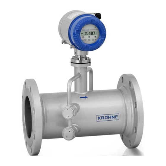
OPTISONIC 7060 System Components The OPTISONIC 7060 measuring system consists of the hardware components, • Meter body • Ultrasonic transducers • CONVERTER (signal processing unit) Fig. 2.3: OPTISONIC 7060 Converter Flange Flowmeter body Indication of positive flow direction Transducer holder 2.3.1... -
Page 12: Ultrasonic Transducers
OPTISONIC 7060 2.3.2 Ultrasonic Transducers The OPTISONIC 7060 ultrasonic transducers are optimised to suit the system requirements. The high quality of the transducer parameters provides the basis for accurate and highly stable propagation time measurements with nanosecond precision. The ultrasonic transducers are of an intrinsically safe design (class "ia"). - Page 13 OPTISONIC 7060 The connection terminals for the power supply and field connections are located on the back of the CONVERTER in a separate terminal box (see Section 3.4.4). The electronics units are mounted in a housing certified to EN 50018 or IEC 60079-1 with type of protection "d"...
-
Page 14: Operating Modes And Signal Output
OPTISONIC 7060 Operating modes and signal output The OPTISONIC 7060 measuring system has the following operating modes: Measurement Normal, fault-free system operation. The pulse and switching outputs, as well as the current output are updated periodically. The “Warning” status signal may be set automatically by the system in the course of the self-diagnosis (for details see Section 2.6). - Page 15 OPTISONIC 7060 The digital output 2 is assigned at the factory with the status signal “Check requested”, and digital output 3 the status signal “Direction of flow”. As a standard, the LCD shows the two major counters, one for each direction of flow.
-
Page 16: Self-Diagnosis
OPTISONIC 7060 Self-diagnosis In the measurement mode, the ratios of sound and path velocities, amplification settings, and signal-to-noise are continuously monitored. If these parameters deviate from a preset range, a warning signal is generated. This enables immediate measures to be taken to prevent possible system malfunctions. -
Page 17: Event Logging
OPTISONIC 7060 Event logging Important system events (max. 250) are stored in a verification logbook. Each entry consists of the event, time stamp and the valid volume counter value along with acknowledgement status present at the time the event occurred. The events are logged continuously in the order they occur and, each event can be acknowledged manually. -
Page 18: Configurations
OPTISONIC 7060 Configurations Output Terminal Assignment AO 0 31, 32 Measured value (current signal 4..20 mA) fault current signal at configuration or malfunction DO 1 51, 52 • Measured value (frequency signal) • Direction of flow • Malfunction • Check requested •... -
Page 19: Assembly And Installation
General Notes 3.1.1 Delivery The OPTISONIC 7060 is delivered in a pre-assembled condition in robust packaging. When unpacking the device, check for possible damage in transit. Pay particular attention to the interior of the meter body, any visible transducer components and the sealing surfaces of the flanges. Any damage must be documented and reported to the manufacturer immediately. -
Page 20: Transport And Storage
Measuring location • The OPTISONIC 7060 can be installed in customary straight inlet and outlet pipes. The adjacent pipes must have the same nominal width as the meter body. The internal diameter can be derived from the marked flange standard and the type key information (Appendix, Table 8.2). -
Page 21: Mechanical Installation
OPTISONIC 7060 Typical installation configuration: Fig. 3.2: OPTISONIC 7060 installation in the pipeline for unidirectional use Temperature measurement point The choice of the installation configuration depends on type and extent of the flow disturbance at the installation position (according to TR G13). -
Page 22: Choosing Flanges, Seals And Other Parts
An arrow on the meter body indicates the main direction of flow. It is recommended to install the OPTISONIC 7060 as indicated by this arrow id the device is to be used for unidirectional flow applications. If the device is to be used in the bidirectional mode, the arrow indicates the positive direction of flow. -
Page 23: Converter Alignment
OPTISONIC 7060 3.3.3 CONVERTER alignment The CONVERTER can be turned to a position which provides a good view on the display and good conditions for cable routing (see Fig. 3.4). A stop on the housing prevents the CONVERTER from being turned more than 330 . This aims to protect the cables from the meter body from damage. -
Page 24: Electrical Installation
0.5 mm² / 1.5 mm² sectional area Maximum cable length Depending on loop resistance; min. Peak current 150 mA input voltage at the OPTISONIC 7060: 12 V Cable diameter 6 ... 12 mm Fixing range of the cable glands Digital output / current output... - Page 25 OPTISONIC 7060 Serial port Specification Notes (RS485) Type of cable Twisted pair, shielded, impedance Connect shielding at other end to approx. 120 Ω ground terminal Min./ max. cross- 2 x 0.5 mm sectional area Maximum cable length 100 m at 0.5 mm²...
-
Page 26: Checking The Cable Loops
10 minutes after the system has been switched off. • Incorrect cabling may cause the OPTISONIC 7060 to fail. This will lead to the annulment of any warranty claims. The manufacturer excludes any liability for consequential damage. -
Page 27: Terminal Box On The Converter
OPTISONIC 7060 3.4.4 Terminal box on the CONVERTER Open the rear housing cover. • Loosen the securing bracket using a 3 mm Allan key. • Turn the rear housing cover in a counter-clockwise direction and take it off. A schematic wiring diagram is provided on the inside of the rear housing cover (see also Appendix, Section 8.3). - Page 28 OPTISONIC 7060 Fig. 3.7: Terminal box on the rear of the CONVERTER Power supply, 2x1,5mm2 (UYCY or equivalent) Digital output / current output, 4 x 2 x 0,5 mm2 (UYCY [TP] or equivalent) Modbus, 4 x 2 x 0,5 mm2 (UYCY [TP} or equivalent) HSK-K cable glands, M20 x 1,5 plastic (EU) or ½...
-
Page 29: Connecting The Optisonic 7060 For Use In Non-Hazardous Areas
OPTISONIC 7060 3.4.5 Connecting the OPTISONIC 7060 for use in non-hazardous areas Assign the terminals in the CONVERTER terminal box (see Fig. 3.7) in accordance with the following table. Terminal box Power supply Field connections (10-channel terminal strip) Fig. 3.8: Terminal assignment for use in non-hazardous areas... -
Page 30: Operation In Hazardous Areas In Accordance With Directive 94/9/Ec (Atex)
The power supply and field connections are designed with the increased type of protection ("e"). The transducer connections are of an intrinsically safe design ("ia"). All screw-type terminals as well as air and creepage distances of the OPTISONIC 7060 comply with EN 50019. - Page 31 Terminal assignment Assign the terminals in the CONVERTER terminal box (see Fig. 3.7) in the same way as for the OPTISONIC 7060 in non-hazardous areas (see table in Section 3.4.5). Important The protective conductor must not be connected within the hazardous area. For...
- Page 32 OPTISONIC 7060 Fig. 3.9: Explosion protection of the OPTISONIC 7060 components Power supply I/O connections Electrical & mechanical installation manual 730962.31.00 page 32 of 52...
- Page 33 OPTISONIC 7060 Safety-relevant data of inputs and outputs Output circuit Intrinsically safe EEX ia IIA / IIB / IIC Non-intrinsically safe U = 253 V Active current output = 22.1 V = 18 V Terminals 31/32 = 35 mA EEx ia IIA...
-
Page 34: Operation In Hazardous Areas To North American Guidelines (Csa)
OPTISONIC 7060 3.4.7 Operation in hazardous areas to North American Guidelines (CSA) The system must be installed as shown in Fig. 8.3 to Fig. 8.5 in the appendix. The notes provided in Fig. 8.3 and Fig. 8.4 must be observed at all times. -
Page 35: Operation Of The Converter
OPTISONIC 7060 Operation of the converter Operation and menu structure of the CONVERTER with LCD 4.1.1 Operation The current measurement, volume counter, and diagnosis values can be displayed on the two-line LCD on the front of the CONVERTER. You can select the values you want to display using a magnetic pen while the front cover is kept closed or using the buttons while the front cover is open (see Fig. -
Page 36: Menu Structure
OPTISONIC 7060 • STEP control panel/ button Used to scroll forward in the menu. • DATA control panel/ button Used to scroll backward in the menu. • ENTER function Used to select a menu level, to acknowledge log book entries and to reset the error volume counter. - Page 37 OPTISONIC 7060 Electrical & mechanical installation manual 730962.31.00 page 37 of 52...
- Page 38 OPTISONIC 7060 Electrical & mechanical installation manual 730962.31.00 page 38 of 52...
-
Page 39: Definition Of Measured Value Displays
OPTISONIC 7060 4.1.3 Definition of measured value displays Each line of the LCD can be configured separately as regards the measured value shown. In addition, the display lines may be configured with a multiplex layout (shifted LCD content). If this configuration is active, the two display contents are shown alternately (display changes every 5 s). -
Page 40: Definition Of Log Book Entries
OPTISONIC 7060 4.1.4 Definition of log book entries 1. Classification The entries are distinguished into three classes and identified by the initial character in the first line. • “I” Information • “W” Warning • “E” Error/ malfunction 2. Type of occurrence •... -
Page 41: Acknowledgement Of A Log Book Entry
OPTISONIC 7060 Name Class Description Value Output range The current measured value can no longer be represented by the pulse output, because the maximum W Output output. frequency was reached. Measurement More than one path must be substituted by the... -
Page 42: Verification And Commissioning
Section 6. Fasten the magnetic pen which is part of the measuring system and which is used to operate the LCD on the CONVERTER using the strap provided on the OPTISONIC 7060 so that it cannot be lost. -
Page 43: Pressure Testing Of A Gas Pipeline With Liquid (Water)
Pressure testing of a gas pipeline with liquid (water) For example when a pipeline in which the OPTISONIC 7060 is installed will be pressure tested with a liquid (water) the following precautions must be taken to prevent the transducers from getting wet: •... -
Page 44: Maintenance
Routine checks You can check the front panel of the OPTISONIC 7060 to ensure that the system is functioning properly (see Section 4.3). The routine checks relate to the following values (see also the table below and Section 6). - Page 45 Deviations from the standard values specified in the table can indicate a malfunction. In addition to diagnosing the error (as described in Section 6), you can also create a diagnosis and status log and send this to KROHNE for analysis (see software manual). Electrical & mechanical installation manual 730962.31.00...
-
Page 46: Troubleshooting
OPTISONIC 7060 Troubleshooting If the routine checks described in Section 5.2 or the functional checks described in Section 4.1.2 indicate that the device is not functioning properly, the following table will help you diagnose the fault. If you still cannot find the cause for the fault, you can use the ALTO IV program to carry out a more detailed fault diagnosis (see software manual, service manual). -
Page 47: Atex / Csa Converter Terminal Assignment
OPTISONIC 7060 ATEX / CSA converter terminal assignment Converter terminal assignments ATEX Fig. 8.1: Terminal assignment in accordance with ATEX IIA Fig. 8.2: Terminal assignment in accordance with ATEX IIC Electrical & mechanical installation manual 730962.31.00 page 47 of 52... -
Page 48: Converter Terminal Assignments Csa
OPTISONIC 7060 Converter terminal assignments CSA Fig. 8.3: Terminal assignment in accordance with CSA Group D Fig. 8.4: Terminal assignment in accordance with CSA Group BCD Electrical & mechanical installation manual 730962.31.00 page 48 of 52... - Page 49 OPTISONIC 7060 Fig. 8.5: Control drawing CSA 781.00.02 (page 1) Electrical & mechanical installation manual 730962.31.00 page 49 of 52...
- Page 50 OPTISONIC 7060 Fig. 8.6: Control drawing CSA 781.00.02 (page 2) Electrical & mechanical installation manual 730962.31.00 page 50 of 52...
- Page 51 OPTISONIC 7060 Fig. 8.7: Control drawing CSA 781.00.02 (page 3) Electrical & mechanical installation manual 730962.31.00 page 51 of 52...
- Page 52 FAX: +49(0)203-301 389 FAX: +39(0)2-43 00 66 66 FAX: +41(0)61-638 30 40 e-mail: export@krohne.de e-mail: info@krohne.it e-mail: info@krohne.ch China KROHNE Measurement Instruments Co. Ltd. Room 7E, Yi Dian Mansion Korea United Kingdom 746 Zhao Jia Bang Road Hankuk KROHNE KROHNE Ltd.
Need help?
Do you have a question about the OPTISONIC 7060 and is the answer not in the manual?
Questions and answers