
Subscribe to Our Youtube Channel
Summary of Contents for SIGNALCORE SC5511A
- Page 1 SC5511A 100 MHz to 20 GHz RF Signal Source USB, SPI and RS-232 Interfaces Operating & Programming Manual www.signalcore.com...
-
Page 2: Table Of Contents
Warnings Regarding Use of SignalCore Products ................... 3 Getting Started ....................4 Unpacking ............................... 4 Verifying the Contents of your Shipment ....................4 Setting Up and Configuring the SC5511A ....................4 Indicator LEDs USB Connector Signal Connections Theory and Operation ..................8 RF Generation ............................ - Page 3 SPI Interface USB Interface Default Startup Mode ........................... 12 Setting the SC5511A: Configuration Registers ........... 13 Table 5. Configuration registers...................... 13 Table 6. Register 0x01 INTIALIZE (1 Byte) ..................15 Table 7. Register 0x02 SET_SYS_ACTIVE (1 Byte) ................15 Table 8.
- Page 4 Table 36. Register 0x01F RF2_FREQUENCY (2 Bytes) ..............21 Table 377. Register 0x47 SYNTH_SELF_CAL (1 Byte) ..............21 Querying the SC5511A: Query Registers ............22 Table 38. Query registers........................ 22 Table 39. Register 0x20 GET_RF_PARAMETERS (1 Byte, 5 Bytes) ..........22 Table 40.
-
Page 5: Important Information
Please contact SignalCore if errors are suspected. In no event shall SignalCore be liable for any damages arising out of or related to this document or the information contained in it. -
Page 6: Copyright & Trademarks
SignalCore, Incorporated respects the intellectual property rights of others, and we ask those who use our products to do the same. Our products are protected by copyright and other intellectual property laws. Use of SignalCore products is restricted to applications that do not infringe on the intellectual property rights of others. -
Page 7: Recycling Information
Laboratory Equipment include EN 61326-1:2013 and EN 55011:2009 for EMC, and EN 61010-1 for product safety. Recycling Information All products sold by SignalCore eventually reach the end of their useful life. SignalCore complies with EU Directive 2012/19/EU regarding Waste Electrical and Electronic Equipment (WEEE). Warnings Regarding Use of SignalCore Products... -
Page 8: Getting Started
All SignalCore products ship in antistatic packaging (bags) to prevent damage from electrostatic discharge (ESD). Under certain conditions, an ESD event can instantly and permanently damage several of the components found in SignalCore products. Therefore, to avoid damage when handling any SignalCore hardware, you must take the following precautions: •... -
Page 9: Indicator Leds
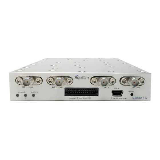
The SC5511A is a core module-based RF signal source with all I/O connections and indicators located on the front face of the module as shown in Figure 1. Each location is discussed in further detail below. Indicator LEDs The SC5511A provides visual indication of important modes. There are three LED indicators on the unit. -
Page 10: Usb Connector
Not internally connected USB Connector The SC5511A uses a mini-USB Type B connector (for USB communication) and a micro-HDMI (for SPI or RS-232 communication, depending on the version ordered) to communicate with the device. The USB port uses the standard USB 2.0 protocol found on most host computers. The pinout of this connector,... - Page 11 Excess liquid alcohol trapped inside the connector may take several days to fully evaporate and may degrade measurement performance until fully evaporated. Tighten all SMA connections to 5 in-lb max (56 N-cm max). SC5511A User Manual Rev 1.7.0...
-
Page 12: Theory And Operation
Figure 2. Block diagram of the SC5511A. RF Generation The SC5511A is a 100 MHz to 20 GHz low phase noise and low spur synthesizer, using a hybrid architecture comprising of phase lock, harmonic generation, and a DDS functions. Coarse tuning is accomplished by PLL and harmonic generators, while fine tuning is accomplished with the variable modulus DDS, providing exact frequency generation. -
Page 13: Amplitude Control
The internal EEPROM is not directly accessible for users to store data. Modes of RF Generation The SC5511A has both single fixed tone and list mode operation for channel 1. In single fixed tone mode, it operates as a normal synthesizer where the user writes the frequency (RF_FREQUENCY) register to change the frequency. -
Page 14: Sweep Function
500 s. The amplitude computational time alone is close to 350 s. If the sweep is over a narrow range, it is best to disable the automatic power leveling feature, allowing faster frequency sweeps. By default whenever the frequency is SC5511A User Manual Rev 1.7.0... -
Page 15: List Cycles
This trigger pulse can be sent on the completion of every step frequency or on the last frequency of a sweep cycle. This trigger signal is present on pin 20 (TRIGOUT). SC5511A User Manual Rev 1.7.0... - Page 16 Communication Interfaces USB interface is common on the SC5511A, while an alternative interface option is SPI or RS232. As both the SPI and RS232 utilize the same internal communication device, and thus the same connector pins, only one option is possible.
- Page 17 Frequency Word (Hz) [31:24] [39:32] Frequency Word (Hz) [39:32] [7:0] Time (500us) [7:0] [15:8] Time (500us) [15:8] LIST_DWELL_TIME 0X09 [23:16] Time (500us) [23:16] [31:24] Time (500us) [31:24] [7:0] Count Word [7:0] LIST_CYCLE_COUNT 0X0A [15:8] Count Word [15:8] SC5511A User Manual Rev 1.7.0...
- Page 18 Open RESERVED 0x1D [7:0] Open Open Open Open Open Open Open Open RF2_STANDBY 0x1E [7:0] Open Open Open Open Open Open Open Open [7:0] Frequency Word (MHz) [7:0] RF2_FREQENCY 0x1F [15:8] Frequency Word (MHz) [15:8] SC5511A User Manual Rev 1.7.0...
- Page 19 0x1A. 1 = Sweep/list mode. In this mode writing to register 0x10 will be unresponsive. This register must be called first for sweep/list triggering to function. [7:1] Unused Set all bits to 0. SC5511A User Manual Rev 1.7.0...
- Page 20 To exit the stepping state and stop before reaching the end of a cycle, a software trigger must to be sent or a change in the RF mode to single fixed tone needs to be made. SC5511A User Manual Rev 1.7.0...
- Page 21 32 Set the dwell time at each step frequency. The Dwell time is incremented in 500 s increments. For example, to produce a 10 ms dwell time the value written to this register is 20d. SC5511A User Manual Rev 1.7.0...
- Page 22 Table 19. Register 0x0E LIST_BUF_MEM_TRNSFER (1 Byte) Type Name Width Description Transfer Direction 1 0 = Transfers the contents of the list buffer into EEPROM memory. The size of the transfer is set by the list frequency points. SC5511A User Manual Rev 1.7.0...
- Page 23 RF1 Auto leveling 1 0 = power is leveled on frequency change 1 = power is not leveled on frequency change with explicitly calling register 0x11 (RF_LEVEL) [7:1] Unused 7 Set all bits to 0 SC5511A User Manual Rev 1.7.0...
- Page 24 ALC DAC value can be read back via register 0x25 [15:14] Unused 2 Set all bits to 0. Table 31. Register 0x01A Reserved (1 Byte) Type Name Width Description [7:0] Reserved Table 32 Register 0x1B STORE_DEFAULT_STATE (1 Byte) Type Name Width Description SC5511A User Manual Rev 1.7.0...
- Page 25 Table 36. Register 0x01F RF2_FREQUENCY (2 Bytes) Type Name Width Description [14:0] Frequency (MHz) 14 Frequency word in MHz; 25 to 3000 Table 377. Register 0x47 SYNTH_SELF_CAL (1 Byte) Type Name Width Description [7:0] Unused 8 Set all bits to 0. SC5511A User Manual Rev 1.7.0...
- Page 26 0x05 = Sweep Cycle Count (4 valid bytes return) 0x06 = Sweep List Buffer Pts (4 valid bytes return) 0x07 = Current RF1 level 0x08 = Current RF2 Freq(2 valid bytes return) 0x0A = signal phase (firmware > Version 2.5) SC5511A User Manual Rev 1.7.0...
- Page 27 1 0 = 10 MHz, 1 = 100 MHz [25] Operate: ext_ref_detect 1 1 = reference source at ref port [24] Operate: ext_ref_lock 1 1 = lock to external sources is enabled [23] Operate: RF1_enable 1 1 = RF1 output is enabled SC5511A User Manual Rev 1.7.0...
- Page 28 Hardware Revision – typecast to 32-bit float Firmware Revision – typecast to 32-bit float Manufacture Date – unsigned 32-bit [31:24] Year (last two digits) [23:16] Month [15:8] Day [7:0] Hour [7:0] Invalid data 8 zeros SC5511A User Manual Rev 1.7.0...
- Page 29 40 Set all bits to 0. Use of this register is only available for the SPI interface. [39:0] Request Data 40 The data clocked back are the contents requested by the 0x20 to 0x25 registers. SC5511A User Manual Rev 1.7.0...
- Page 30 USB interface is available on the device. USB Configuration The SC5511A USB interface is USB 2.0 compliant running at Full Speed, capable of 12 Mbits per second transfer rates. The interface supports three transfer or endpoint types: •...
- Page 31 5 bytes the tail bytes are padded with zeros. USB Driver API The SC5511A USB driver provided by SignalCore is based on libusb-1.0 (www.libusb.org) and its API library is available for the Windows and Linux operating systems.
- Page 32 C header file, sc5511a.h. These constants and types are useful not only as an include for developing applications using the SC5511A API, but also for writing device drivers independent of those provided by SignalCore.
-
Page 33: Sc5511A_Open_Device
(num_of_devices == 0) printf("No signal core devices found or cannot not obtain serial numbers\n"); for(i = 0; i<MAXDEVICES;i++) free(device_list[i]); free(device_list); return printf("\n There are %d SignalCore %s USB devices found. \n \n", num_of_devices, SCI_PRODUCT_NAME); i = 0; while ( i < num_of_devices) printf("... -
Page 34: Sc551A_Reg_Write
= sc5511a_reg_read(dev_handle, GET_DEVICE_STATUS, 0x00, &frequency); Function: sc5511a_set_freq Definition: sc5511a_set_frequency (sc5511a_device_handle_t dev_handle, unsigned long long int freq) Input: sc5511a_device_handle_t *dev_handle (handle to the opened device) unsigned long long int frequency (frequency in Hz) Description: sc5511a_set_frequency sets RF1 frequency. SC5511A User Manual Rev 1.7.0... -
Page 35: Sc5511A_Set_Signal_Phase
Function: sc5511a_set_rf_mode Definition: sc5511a_set_rf_mode(sc5511a_device_handle_t dev_handle, unsigned char rf_mode) Input: sc5511a_device_handle_t *dev_handle (handle to the opened device) unsigned char rf_mode (set RF mode of RF1) Description: sc5511a_set_rf_mode sets RF1 to fixed tone or sweep. SC5511A User Manual Rev 1.7.0... -
Page 36: Sc5511A_List_Mode_Config
(Time in 500 µs increments) Description: sc5511a_list_dwell_time stet the sweep/list dwell time at each frequency point. Dwell time is in 500 µs increments (1 = 500 µs, 2 = 1 ms, etc.). SC5511A User Manual Rev 1.7.0... -
Page 37: Sc5511A_List_Cycle_Count
*dev_handle, unsigned char transfer_mode) Input: sc5511a_device_handle_t *dev_handle (handle to the opened device) unsigned char transferMode (transfer to EEPROM or RAM) Description: sc5511a_list_buffer_transfer transfers the frequency list buffer from RAM to EEPROM or vice versa. SC5511A User Manual Rev 1.7.0... -
Page 38: Sc5511A_List_Soft_Trigger
Definition: int sc5511a_set_auto_level_disable(sc5511a_device_handle_t *dev_handle, unsigned char disable) Input: sc5511a_device_handle_t *dev_handle (handle to the opened device) unsigned char disable (disable leveling) Description: sc5511a_set_auto_level_disable disables the leveling compensation after the frequency is changed for channel RF1. SC5511A User Manual Rev 1.7.0... -
Page 39: Sc5511A_Set_Alc_Mode
*dev_handle, unsigned short dac_value) Input: sc5511a_device_handle_t *dev_handle (handle to the opened device) unsigned short dac_value (DAC value to be written) Description: sc5511a_set_alc_dac set the value of the ALC DAC to make amplitude adjustments. SC5511A User Manual Rev 1.7.0... -
Page 40: Sc5511A_Store_Default_State
Allow 2-3 seconds for the calibration routing to execute, and upon completion the device will reset. The status indicator of RF1 will go off, then red, then amber, and then finally green. SC5511A User Manual Rev 1.7.0... -
Page 41: Sc5511A_Get_Rf_Parameters
(dev_handle, dev_status); if(dev_status->pll_status.ref_100_pll_ld) printf("The 100 MHz is phase-locked \n"); else printf("The 100 MHz is not phase-locked \n"); free(deviceStatus); Function: sc5511a_get_device_info Definition: sc5511a_get_device_info(sc5511a_device_handle_t*dev_handle, device_info_t *device_info) Input: sc5511a_device_handle_t*dev_handle (handle to the opened device) Output: device_info_t *device_info (device information) SC5511A User Manual Rev 1.7.0... -
Page 42: Sc5511A_List_Buffer_Read
*dac_value) Input: sc5511a_device_handle_t*dev_handle (handle to the opened device) Output: unsigned short *dac_value (DAC value) Description: sc5511a_sc5511a_get_alc_adc retrieves the current value of the ALC DAC which set the power level of channel RF1. SC5511A User Manual Rev 1.7.0... - Page 43 0, pin 16 of the interface connector must be pulled low to ground as the device is powered on or as the reset line (pin 14) is toggle low-high. If pin 16 is pulled high or left unconnected, mode 1 is select. MOSI MISO Figure 3. SPI Mode 0 shown. SC5511A User Manual Rev 1.7.0...
- Page 44 The SPI transfer size (in bytes) depends on the register being targeted. The MSB byte is the command register address as noted in the Setting the SC5511A: Configuration Registers section. The subsequent bytes contain the data associated with the register. As data from the host is being transferred to the device via the SDI (MOSI) line, data present on its SPI output buffer is simultaneously transferred back, MSB first, via the SDO (MISO) line.
- Page 45 Figure 5 shows the contents of a single 3 byte SPI command written to the device. The Setting the SC5511A: Configuration Registers section provides information on the number of data bytes and their contents for an associated register. There is a minimum of 1 data byte for each register even if the data contents are “zeros”.
- Page 46 *(float*)& in C/C++.Programming the RS-232 Interface The RS-232 version of the SC5511A has a standard interface buffered by an RS-232 transceiver so that it may interface directly with many host devices, such as a desktop computer. The interface connector for RS-232 communication is labeled “Digital I/O”...
- Page 47 As with the configuration registers, it is important that the data byte(s) associated with the query registers are sent even if they are nulls. The returned data length is also detailed in the Querying the SC5511A: Query Registers section. Returned valid data are detailed in Table 46 and Table RS-232 Windows The API for RS-232 control is provided only for the Windows operating system under the api\rs232 \c directory of the installation path.
- Page 48 The SC5511A is factory calibrated and ships with a certificate of calibration. SignalCore strongly recommends that the SC5511A be returned for factory calibration every 12 months or whenever a problem is suspected. The specific calibration interval is left to the end user and is dependent upon the accuracy required for a particular application.
- Page 49 1) Added ability to change the phase of the signal on CH1 with resolution 08-03-18 limitation for lower frequencies. Only for firmware versions 2.5 and Rev 1.5.0 higher. Contact SignalCore for firmware updates. 2) Corrected and updated Table 39. Rev 1.6.0 Function deleted, not applicable.
Need help?
Do you have a question about the SC5511A and is the answer not in the manual?
Questions and answers