Table of Contents
Advertisement
Quick Links
Advertisement
Chapters
Table of Contents

Related Manuals for Yamaha DX7s


Summary of Contents for Yamaha DX7s
- Page 1 YAMAHA DIGITAL PROGRAMMABLE ALGORITHM SYNTHESIZER OWNER’S MANUAL...
-
Page 2: Special Message Section
SPECIFICATIONS SUBJECT TO CHANGE: The information contained in this manual is believed to be correct at the time of printing. Yamaha reserves the right to change or modify specifications at any time without notice or obligation to update existing units. - Page 3 If you are already familiar with the operation of the original DX7, this manual will help you make the transition to the DX7s in short order. On the other hand, if this is your first FM digital instrument, this manual will guide you into the operation of your new synthesizer with easy-to-follow, step-by-step instructions and explanations.
- Page 4 Also, since the DX7s is electronic, you should make sure not to set it too close to equipment (such as a television set) that generates electromagnetic fields. Such proximity could cause both malfunctions in the synthesizer’s digital circuitry and interference noise...
- Page 5 AC Power & Down Time: Whenever the DX7s will not be used for an extended period of time, it is best to protect it from potential disaster. Electrical storms and other natural or man-made disasters can give rise to power surges, which may damage the digital circuitry of your DX7s — even if the power is turned off.
-
Page 6: Table Of Contents
Contents Section 1: Playing the DX7s Getting Started Setting the ROM Cartridge Banks Exploring the DX7s Performance Library Exploring the DX7s Voice Library The Play Modes Using Controllers with the DX7s Section 2: Creating and Storing New Sounds Creating New Sounds... -
Page 7: Section 1: Playing The Dx7S
Playing the DX7s - 1 -... - Page 8 Setting the Volume Slider Setting the ROM Cartridge Banks Inserting the ROM Cartridge Selecting the ROM Banks Exploring the DX7s Performance Library Selecting the Internal Performance Memories The Internal Performance Memories Selecting the Cartridge Performance Memories The Cartridge Performance Memories...
-
Page 9: Getting Started
Getting You can begin to enjoy your DX7s immediately, without poring through a lot of Started complicated electronic theory. All you have to do is take the instrument out of the box and proceed as follows: Making Audio Connections There are three different ways to connect the DX7s to sound reinforcement equipment. - Page 10 Turning on the DX7s After you have made the audio connection of your choice, turn the DX7s on by pressing the power switch located on the right side of the back panel. This is the first display you...
- Page 11 Setting the Volume Slider Since the volumes of the various voices differ, start with a setting in the middle of the slider’s range; adjust later to suit your taste, depending on the voice or voices being played. Volume Slider - 5 -...
- Page 12 3. Look at the diagram on the next page and make the necessary changes before you begin playing. Inserting the ROM Cartridge Before you begin to play your DX7s, insert the supplied ROM cartridge into the cartridge slot: - 6 -...
- Page 13 Selecting the ROM Banks This is the Set Bank LCD display with Bank 2 of the ROM cartridge selected for Voice & Performance data. This is the Set Bank LCD display with Bank 3 of the ROM cartridge selected for Fractional Scaling data. - 7 -...
-
Page 14: Exploring The Dx7S Performance Library
Exploring The Performance Mode is a completely new feature for the DX7s. It allows a number of the DX7s useful performance-oriented features to be stored and recalled instantly. These features will be explained in detail in Sections 2 and Performance the steps below, and explore the richness the new sounds available in the Internal and ROM Cartridge memories. - Page 15 The Internal Performance Memories These are the Performance Memories loaded into the DX7s when it is shipped from the factory. Since these memories can be adjusted, your DX’s Internal Memory may contain different data. If so, reload the Internal Voice &...
- Page 16 Selecting the Cartridge Performance Memories The LCD display will show the number and name of the selected Performance memory. -10-...
- Page 17 Bank 4 of the supplied ROM cartridge contains the Voice & Performance Memory loaded into the DXs Internal Memory when it is shipped from the factory. Bank 2 contains an entirely different set of Voice & Performance data. The Cartridge Performance Memories Performance Name SuperBass...
-
Page 18: Exploring The Dx7S Voice Library
Exploring The voices in the DX7s were created using techniques like those used on the original the DX7s DX7. There are a number of new features available in Voice Mode (most extensions Voice discussed in detail in Sections 2 and 4... - Page 19 These are the Voice Memories loaded into the DX7s when it is shipped from the factory. Since these memories can be adjusted, your DX’s Internal Memory may contain different data. If so, reload the Internal Voice & Performance data from bank 1 supplied ROM cartridge (see page 70).
- Page 20 Selecting the Cartridge Voice Memories As explained on page 6, the DX7s ROM cartridge contains several banks. To hear the cartridge voices, make sure that the Voice/Performance bank is set to bank 2 of the ROM cartridge (see page 7 for instructions on how to change the cartridge banks).
- Page 21 Bank 4 of the supplied ROM cartridge contains the Voice & Performance Memory loaded into the DX’s Internal Memory when it is shipped from the factory. Bank 2 contains an entirely different set of Voice & Performance data. The Cartridge Voice Memories 1 SuperBass 2 StringBass 3 SkweekBass...
-
Page 22: The Play Modes
Play Modes operate. Read on: Voice Mode and Performance Mode The DX7s has two different play modes: Voice Mode and Performance Mode. As you have just seen, the Voice Mode is where you recall the 64 Internal Voice memories and the 64 Cartridge Voice memories. -
Page 23: Using Controllers With The Dx7S
The Breath Controller plugs into the mini-jack to the left of the Phones plug on the front of the DX7s. It allows you a great deal of expressive control over the shape of the sounds you play on the keyboard. Try using the Breath Controller in conjunction with Internal Voice #9. - Page 24 The Foot Controllers plug into the two Foot Controller plugs on the back panel of the DX7s. They can give you continuous control over a number of aspects of the sounds. Try using Foot Controller 1 with Cartridge Performance #25 or Internal Performance #12 (from bank 2 of the ROM).
-
Page 25: Section 2: Creating And Storing New Sounds
Creating and Storing New Sounds - 19 -... - Page 26 Creating New Sounds Contents Editing and Edit Mode Entering Edit Mode Editing Performance and Voice Data Using the Cursor Buttons and the Data Entry Buttons/Slider Edit/Compare Edit Button Quick Reference Guide Saving New Sounds Memory Protection Turning Memory Protect Off Voice and Performance Memory Storing Performance Data to Internal or Cartridge Memory Storing Voice Data to Internal or Cartridge Memory...
-
Page 27: Creating New Sounds
Editing is the process of changing various settings of a Voice or Performance memory. In the DX7s, this is accomplished in Edit Mode. Usually, you will use Edit Mode to create a new Voice or Performance setup, but you can also use it to find out the parameter values for the factory preset Voices and Performance setups. -
Page 28: Entering Edit Mode
Entering Edit Mode In the Edit Mode, you can edit both Voice and Performance parameters. In the above procedure, the Edit Mode is entered after the Edit button is pressed in step #1. At that time, you can push any or all of the buttons indicated as many times as necessary to make the desired edits. -
Page 29: Editing Performance And Voice Data
Editing Performance and Voice Data After entering one of the Edit Modes, use the number buttons to access the parameter whose value you wish to change. Each number button calls up a variety of parameters, often through the use of multiple LCD screen displays. A complete set of these screen displays will be given at the beginning of Section 3 (for Performance parameters) and Section 4 (for Voice parameters). -
Page 30: Edit Button Quick Reference Guide
Edit Button Quick Reference Guide Voice parameters are discussed in more detail in Section 4. Voice parameters are discussed in more detail in Section 4. - 24 -... - Page 31 Performance parameters are discussed in more detail in Section 3. Utility parameters are discussed in more detail in Section 5. MIDI parameters discussed in more detail in Section 6. -25 -...
-
Page 32: Saving New Sounds
Memory. To do so, proceed as follows: Memory Protection Each time the DX7s is turned on, it automatically powers up with both the Internal and the Cartridge Memory Protect feature turned on. Before you can save data, you must turn off this automatic memory protection. -
Page 33: Storing Performance Data To Internal Or Cartridge Memory
Storing Performance Data to Internal or Cartridge Memory Storing Voice Data to Internal or Cartridge Memory - 27 -... - Page 34 - 28 -...
-
Page 35: Section 3: Using The New Performance Features
Using the New Performance Features - 29 -... - Page 36 Performance Edit Buttons Contents Button 27 LCD Displays Button 28 LCD Displays Button 29 LCD Displays Basic Performance Parameters Total Volume Key Shift EG Forced Damp Performance Name Voice Number Performance Controllers Sustain Footswitch (FS 1) Footswitch 2 (FS 2) Continuous Sliders FM Parameters Assignable to CS1 and CS2 Micro Tuning...
-
Page 37: Performance Edit Buttons
Performance All of the Performance Mode parameters are adjusted via the LCD displays called up Edit Buttons using buttons 27 ~ 29. All of the these buttons call up multiple LCD displays. The charts below show all of the displays called up by each button, and provide a complete list of parameters and value ranges. -
Page 38: Button 29 Lcd Displays
Button 29 LCD Displays - 32 -... -
Page 39: Basic Performance Parameters
Basic Accessed using buttons 28 and 29, these parameters determine the basic voice Performance relationships in Peformance Mode. Parameters Total Volume This parameter allows you to set an overall volume for each Performance memory. If you desire, you can use this setting to balance the levels of your Performance memories, so that constant Volume Slider or mixer adjustments are not necessary. -
Page 40: Eg Forced Damp
EG Forced Damp Even though the DX7s is a 16-voice synthesizer, these voices can be used up quickly when you use a Sustain Footswitch pedal. When you do exceed the DX’s note capacity, the first notes played will stop sounding to make way for the new notes being played. -
Page 41: Performance Name
Since you have a total of ten characters to define your Peformance Memory, make sure that your Performance Name conveys the basic approach of the specific Performance Memory. Performance Name You can enter a Performance Name of up to ten characters. To do so, follow the instructions below. -
Page 42: Performance Controllers
Performance The DX7s features a greatly expanded set of controller options. The settings for Controllers Footswitches 1 and 2 and Continuous Sliders 1 and 2 are adjusted in Performance Edit Mode, using button 27. (The other controller settings are accessed in voice parameters.) Sustain Footswitch (FS 1) Footswitch 1 is set to operate as a sustain pedal. -
Page 43: Continuous Sliders
The Continuous Sliders provide a new avenue for exploration of real-time timbral control. Continuous Sliders The two Continuous Sliders give you access to real-time control of FM voice parameters. There are a total of 103 different possibilities: FM Parameters Assignable to CS 1 and CS2 DATA ENTRY slider highest position l OP 6... -
Page 44: Micro Tuning
Micro Tuning is another new feature for the DX7s. It offers the possibility of performing music using tuning and intonation systems other than Equal Temperament (which is the current standard tuning for both pianos and synthesizers). Micro Tuning data is accessed using button 29. - Page 45 Entering the Micro Tuning Edit Mode Editing Micro Tuning Data Storing Micro Tuning Data - 39 -...
- Page 46 - 40 -...
-
Page 47: Section 4: Using The New Voice Features
Using the New Voice Features - 41 -... - Page 48 Voice Edit Buttons Contents Button 7 LCD Display Button 8 LCD Display Button 9 LCD Display Button 10 LCD Displays Button 11 LCD Display Button 12 LCD Display Button 13 LCD Display Button 23 LCD Displays Button 24 LCD Displays Button 25 LCD Displays Button 26 LCD Displays Basic Voice Editing Functions...
-
Page 49: Voice Edit Buttons
Voice All of the Voice Mode parameters are adjusted via the LCD displays called up using Edit Buttons buttons 7 - 13 and 23 - 26. Many of the these buttons call up multiple LCD displays. The charts below show all of the displays called up by each button, and provide a complete list of parameters and value ranges. -
Page 50: Button 8 Lcd Display
Button 8 LCD Display Button 9 LCD Display - 44 - Oscillator Mode (ratio, fixed) Frequency Coarse ( v a r i e s Frequency Fine (varies) Oscillator Detune (-7 ~ +7) Rate Scaling (0 ~ 7) Envelope Generator Rates 1 ~ 4 (0 ~ 99) Envelope Generator Levels 1 ~ 4 (0 ~ 99) -
Page 51: Button 10 Lcd Displays
Button 10 LCD Displays - 45 -... -
Page 52: Button 11 Lcd Display
Button 11 LCD Display - 46 - Key Velocity (0 ~ 7) Amplitude Modulation Sensitivity (0 ~ 7) Pitch Modulation Sensitivity (0 ~ 7) -
Page 53: Button 12 Lcd Display
Button 12 LCD Display - 47 - LFO Wave (triangle, saw down, saw up, square, sine, s/hold) LFO Speed (0 ~ 99) LFO Delay (0 ~ 99) LFO Mode (single, multi) LFO Pitch Modulation Depth (0 ~ 99) LFO Amplitude Modulation Depth (0 ~ 99) LFO Key Sync (off, on) -
Page 54: Button 13 Lcd Display
Button 13 LCD Display Button 23 LCD Displays -48- Pitch Envelope Octave Range (1/2, 1,2,8) Pitch Envelope Velocity (off, on) Pitch Envelope Rate Scaling (0 ~ 7) Pitch Envelope Rates 1 ~ 4 (0 ~ 99) Pitch Envelope Levels 1 ~ 4 (0 ~ 99) Key Mode Assign (polyphonic, monophonic,... -
Page 55: Button 24 Lcd Displays
Button 24 LCD Displays -49- Pitch Bend Mode (normal, lowest, highest, key on) Pitch Bend Range (0 ~ 12) Pitch Bend Step (0 ~ 12) Portamento Mode (Poly: sus-key, p retain, sus-key p follow) (Mono: fingered porta, full time porta) Portamento Time (0 ~99) Portamento Step... -
Page 56: Button 25 Lcd Displays
Button 25 LCD Displays - 50 - Aftertouch EG Bias (0 ~ 99) Aftertouch Pitch Bias (-50 ~ +50) Modulation Wheel Pitch Modulation Depth (0 ~ 99) Modulation Wheel Amplitude Modulation Depth (0 ~ 99) Modulation Wheel EG Bias (0 ~ 99) -
Page 57: Button 26 Lcd Displays
Button 26 LCD Displays - 51 - Foot Controller 2 EG Bias (0 ~ 99) Foot Controller 2 Volume (0 ~ 99) MIDI Controller Pitch Modulation Depth (0 ~ 99) MIDI Controller Amplitude Modulation Depth (0 ~ 99) MIDI Controller EG Bias (0 ~ 99) MIDI Controller Volume (0 ~ 99) -
Page 58: Basic Voice Editing Functions
1 ~ 6 and 17 ~ 22. EG Copy The EG Copy function from the original DX7 is retained in the DX7s, and is made easier through the use of buttons 1 ~ 6. Once you have envelope data you want to copy displayed in the LCD, simply press and hold the Store/EG Copy button. -
Page 59: New Voice Parameters
Representative Pitch Enselope Generator shape. The basic voice of the DX7s is almost exactly the same as that of the ori,ginal DX7, assuring complete compatibility between the old and new instruments. To discoser the additional voice parameters of the DX7s, read on. -
Page 60: Key Modes
Key Modes The DX7s offers two Unison Key Modes, which create “fatter” sounds. Since these new Modes use more than one note of the DX’s sixteen-note capacity, they will affect the total number of notes available at any one time:... -
Page 61: Voice Controllers
Most of the Voice Effect parameters are exactly the same as the Function parameters of the original DX7. The new parameters are outlined below. Pitch Bend Modes The Pitch Bend Wheel in the DX7s functions in one of four basic Modes, which operate as follows: Pitch Bend Pitch Bend Modes on the DX7s. -
Page 62: Pitch Bias
Pitch Bias With the new Pitch Bias feature you can use After Touch or the Breath Controller to control the pitch of a voice. When Pitch Bias is set to 0, there is no pitch change. Positive Pitch Bias settings result in an upward bend, while negative Pitch Bias settings cause the pitch to bend down. -
Page 63: Fractional Scaling
DX7 voicing is Level Scaling, which allows Scaling adjustment of each operator’s output over the range of the keyboard. The DX7s offers the possibility of even more subtle control over operator outputs, through Fractional Scaling. Fractional Scaling and Level Scaling Although the DX7’s Level Scaling offers a great deal of interaction between timbre and... - Page 64 Editing Fractional Scaling Data Storing Fractional Scaling Data - 58 -...
-
Page 65: Section 5: Memory Functions
Memory Functions -59 -... - Page 66 Utility Buttons Button 14 LCD Displays Contents Button 15 LCD Displays Memory Types Voice & Performance Memory System Setup Memory Micro Tuning Memory Fractional Scaling Memory Initialized Memory Current Play/Edit Memory Compare/Recall Memory Memory Storage Types Internal Memory Cartridge Memory ROM Cartridge Basic Utility Functions Master Tune...
-
Page 67: Utility Buttons
Utility Buttons All of the memory functions (and related utility functions) are adjusted via the LCD displays called up using buttons 14 and 15. Both of the these buttons call up multiple LCD displays. The charts below show all of the displays called up by each button, and provide a complete list of parameters and value ranges. -
Page 68: Button 14 Lcd Displays
Button 14 LCD Displays - 62 -... - Page 69 - 63 -...
-
Page 70: Memory Types
Memory Types The chart below is a graphic representation of the way all the different DX7s memory areas interact with one another. Since there are many facets to the memory layout of the DX7s, it may look intimidating at first. Once you become more familiar with the instrument, though, you will fjnd the memory layout is much simpler than it first appears. -
Page 71: System Setup Memory
Whenever you call up a Voice Memory or Performance Memory in Play Mode, you are actually sending it to a special location in the DX7s — the current Play/Edit Memory. As the name indicates, this is also the location where Voice or Performance data is edited. In computer terminology, this memory location is often called the Edit Buffer. -
Page 72: Memory Storage Types
The RAM4 Fractional Scaling Memory holds up to 64 Fractional Scalings, which are tied to the 64 Voices in the DX’s Internal Memory. The RAM4 Micro Tuning Memory holds up to 63 Micro Tunings. - 66 - memory, the DX7s offers a number... -
Page 73: Rom Cartridge
The supplied ROM cartridge holds a number of different kinds of DX memory. ROM Cartridge The supplied ROM cartridge contains 4 banks, which can be accessed using button 15 in Edit Mode: The first two banks are Cartridge Voice and Performance data. The third bank contains Fractional Scaling data, and the fourth bank has the original Internal Voice and Performance data. -
Page 74: Basic Utility Functions
Functions Mode, as follows: Master Tune This sets the tuning of the DX7s relative to its internal A-440 reference. Recall Edit These functions can be used to recall Voice, Performance, or Micro Tuning data from the DX’s Compare/Recall Memory. Edit Recall is particularly useful if you forget to save a Voice, Performance, or Micro Tuning and don’t realize it until later. -
Page 75: Cartridge Memory Functions
Fractional Scaling data may be recalled for immediate use. If you create Voice or Performance data that involves Cartridge Memory (for either Fractional Scaling or Micro Tuning), the DX7s will remind you as follows: This symbol signifies that the indicated Performance memory... -
Page 76: Formatting A Ram Cartridge
Formatting a RAM Cartridge Loading Voice & Performance Data from a RAM Cartridge - 70 -... -
Page 77: Section 6: Midi Functions
MIDI Functions - 71 -... - Page 78 MIDI Buttons Button 31 LCD Displays Contents Button 32 LCD Displays System Setup Transmit Channel Receive Channel Omni Mode Local On/Off MIDI IN Control Number CS 1 and CS 2 Controller Numbers Note On/Off Program Change Transmission Program Change Memory After Touch MIDI System Exclusives MIDI Device Number...
-
Page 79: Midi Buttons
MIDI Buttons All of the MIDI functions and parameters are adjusted via the LCD displays called up using buttons 31 and 32. Both charts list of parameters and value ranges. In some cases, the first LCD display in a chart may not be the first one you see. -
Page 80: Button 32 Lcd Displays
Button 32 LCD Displays - 74 -... -
Page 81: System Setup
You set the DX’s MIDI receive channel with this parameter. If you turn this parameter off, all incoming MIDI data will be ignored. Omni Mode When Omni mode is on, the DX7s will receive MIDI data from all of the 16 MIDI channels (the MIDI receive channel is disregarded). Local On/Off If Local is set to off, notes played on the DX7s keyboard will not engage the DX’s... -
Page 82: Note On/Off
“even,” it will only play notes that have even MIDI note numbers. Similarly, if this parameter is set to “odd,” the DX7s will only play notes that have odd MIDI note numbers. This can be used in conjunction with other MIDI instruments to produce a variety of interesting effects. -
Page 83: Midi System Exclusives
MIDI System If you use the DX7s as part of a MIDI system, there are a number of advanced MIDI functions available for your use: Exclusives MIDI Device Number If the DX7s is connected to another Yamaha product, this parameter must be used to set a Yamaha System Exclusive Device Number for MIDI System Exclusive data reception or transmission. -
Page 84: Immediate Midi Program Change Out
All three positions in the LCD must be filled: for example, to send program #1, type in 001. Once you have typed in the third number, the program change you have typed in will be sent over MIDI to the instrument connected to your DX7s. - 78 -... -
Page 85: Appendices
Appendices - 7 9 -... -
Page 86: Appendix 1: Supplemental Information
Appendix 1: As mentioned at the outset, this manual has not attempted to cover all of the functions of the DX7s in exhaustive detail. To do so would have required a manual of large scale and Supplemental density, one in which it would have been very difficult to locate specific information Information needed to begin using the DX7s. -
Page 87: Appendix 2: Bibliography
Appendix 2: Many of the basic functions of the DX7s are the same as those of the original DX7. Since Bibliography there is a wealth of material available on the operation of the original DX7, this manual has focused on the new functions and features. For more information on the parameters and features that the new DX shares with the original DX7, consult the following: DX7 Owner’s Manual. -
Page 88: Midi Implementation Chart
1 =transmit if trasmit channel is not off. 2 =receive if receive channel is not off. 3 =transmit/receive if Exclusive is not off. Mode 1 : OMNI ON, POLY Mode 3 : OMNI OFF. PLOY Model DX7s MIDI Implementation Chart Transmitted 1–16 1–16 1–16 1–16... -
Page 90: Midi Data Format
MIDI DATA FORMAT 1. Transmission Requirements Add-1... - Page 91 2. Transmission Data 2-1. Channel information Transmission is possible only when 1 ~ 16 is specified as the transmission channel. 1) Channel voice message Key ON/OFF Status 1 0 0 1 n n n n ($9n) n=channel No. Note No. 0 k k k k k k k Velocity 0 v v v v v v v ( v...
- Page 92 Note 4) Fractional Scaling Parameter Change Data Operator number operator Note 5) Fractional Scaling Parameter Change Data key group offset C—2 ~C—1 C # — 1 ~ D # — 1 E—1 ~F#—1 G—1 ~A—1 A # — 1 ~ C 0 C # 0 ~ D # 0 ~ F # 0 A # 0 ~C1...
- Page 93 Bulk dump Voice edit buffer Additional voice edit buffer Packed 32 additional voice Packed 32 voice Status 1 1 1 1 n n n n ($F0) ID No. 0 1 0 0 0 0 1 1 ($43) Substatus 0 0 0 0 n n n n ($0n) n=device No.
- Page 94 3. Reception Requirements A d d - 5...
- Page 95 4. Reception Data 4-1. Channel information 1) Channel voice message Key OFF Status 1 0 0 0 n n n n ($8n) Note No. 0 k k k k k k k Velocity 0 v v v v v v v Key ON/OFF Status 1 0 0 1 n n n n ($9n) n=channel No.
- Page 96 2) System exclusive messages Parameter change (Switch remote) Status 1 1 1 1 n n n n ($F0) ID No. 0 1 0 0 0 0 1 1 ($43) Substatus 0 0 0 1 n n n n ($1n) n=device No. Group No.
- Page 97 The 8 types of format are as follows: The 8 types of format are as follows: Data Performance edit buffer Packed 32 performance System setup Micro tuning edit buffer Micro tuning with memory Micro ro tuning in cartridge Fractional scaling edit buffer Fractional scaling in cartridge Data format name Classification name...
-
Page 98: Parameter Chart
5. PARAMETER CHART 5-1. VOlCE PARAMETER (Voice edit buffer) PARAMETER NUMBER OPERATOR 79 100 121 80 101 122 81 102 123 82 103 124 83 104 125 ......................................DATA (INIT) 0 - 9 9... - Page 99 5-2. ADDlTlONAL VOICE PARAMETER (ADDITIONAL VOlCE EDIT BUFFER) P.NO DATA (INIT) 1 (norm) 1 (norm) 1 (norm) 1 (norm) 1 (norm) 1 (norm) 7 (0) 7 (0) 7 (0) 7 (0) 7 (0) 7 (0) ....3 (8oct) 1 (singl) 1 (off...
- Page 100 5-3. PERFORMACNCE PARAMETER (PERFORMANCE EDIT BUFFER /1 PERFORMANCE MEMORY) P.NO DATA (INIT) 0 - 127 (0) 0 - 127 (0) 0 - 74 (EQUAL) 0 - 11 ({C}) 7 (0) 0 - 127 (C3) 1 (OFF) 3 (PORT) 7 (0) 0 - 48 (0) 0 - 48 (0) 0 - 100 (CENTER)
- Page 101 5-4. VOICE MEMORY FORMAT OP6 OP5 OP4 OP3 OP2 OP1 ........................................LFO P.MOD SENS.
- Page 102 5-5. ADDITIONAL VOICE MEMORY BIT6 BIT5 RANDOM PITCH DEPTH PB MODE BIT4 BIT3 BIT2 PEG RANGE PEG SW LFO TRG PB RANGE PB STEP PORT. STEP PORT. TIME MW PMOD MW AMOD MW EG BIAS FC1 PMOD FC1 AMOD FC1 EG BIAS FC1 VOLUME BC PMOD BC AMOD...
- Page 103 5-6. SYSTEM SETUP PARAMETER P.NO D A T A ( I N I T ) 0 - 1 5 ( 0 ) 0 - 1 ( 0 N ) 0- 16 (0) 0- 16 (0) 0 - 1 ( O N ) 9- 31 (11) 9- 31 (12) 5- 31 (13)
- Page 104 5-7. MICRO TUNlNG PARAMETER BYTE KEYNAME 48 CO 96 C2 C#-2 G#-2 G#-2 A#-2 72 C1 120 C3 144 C4 192 C6 240 C8 168 C5 216 C7 Add-15 DATA NOTES 0 - 8 4 0-127 0-10794 0-127 0-10794 0 - 8 4 0-127 0-10794 0-127...
- Page 105 5-8. FRACTIONAL KEY LEVEL SCALING PARAMETER C#-1 - D#-1 F#-1 - A-l A#-1 - C#O - A#0 - C#1 - - A1 A#1 - C#2 - A#2 - C#3 - A#3 - C#4 - - A4 A#4 - C#5 - A#5 - C#6 - - A6...
-
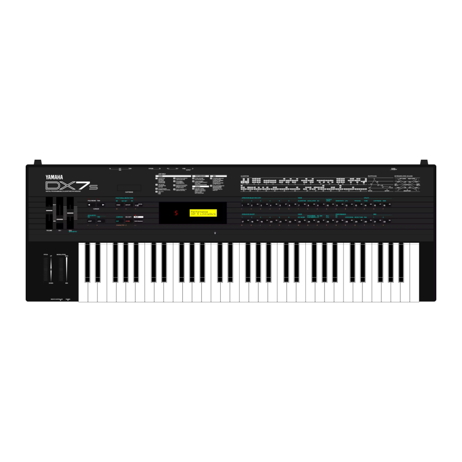
Page 106: Specifications
61 keys (C K e y b o a r d FM tone Generator (6 operators 32 algorythms) Tone Generator Simultaneous Note Output (Reverse priority) 16 notes 64 voices/32 performances, 2 micro tunings, 1 system set-up Internal Memory External ROM Memory 128 voices/64 performances, micro tuning, fractional level scaling, system set-up RAM cartridge (Optional, RAM4) = Internal Memory x 1, or 64 fractional level scaling or 63 micro tuning External Memory... - Page 107 The product has been dropped, or the enclosure of the product has been damaged. 14. When not in use, always turn your Yamaha Digital Mu- sical Instrument equipment “OFF”. The power supply cord should be unplugged from the outlet when the equipment is to be left unused for a long period of time.
- Page 108 (within three meters), interference may occur. This series of Yamaha combo equipment have been type tested and found to comply with the specifications set for a class B computing device in.