Table of Contents
Advertisement
Quick Links
Advertisement
Table of Contents

Related Manuals for Yamaha WK83840


Summary of Contents for Yamaha WK83840
-
Page 2: Important Safety Instructions
CA UT IO N RISK OF ELECTRIC SHOCK DO NOT OPEN CAUTION: TO REDUCE THE RISK OF ELECTRIC SHOCK, DO NOT REMOVE COVER (OR BACK). NO USER-SERVICEABLE PARTS INSIDE. REFER SERVICING TO QUALIFIED SERVICE PERSONNEL. The above warning is located on the top of the unit. IMPORTANT SAFETY INSTRUCTIONS Read these instructions. - Page 3 This product contains a battery that contains perchlorate material. Perchlorate Material—special handling may apply, See www.dtsc.ca.gov/hazardouswaste/perchlorate. (3 wires) • This applies only to products distributed by YAMAHA CORPORATION OF AMERICA. (Perchlorate) (lithium disposal) (class B) (lithium caution)
- Page 4 The device contains no user-serviceable parts. If it should appear to be malfunctioning, discontinue use immediately and have it inspected by qualified Yamaha service personnel. CAUTION Always follow the basic precautions listed below to avoid the possibility of physical injury to you or others, or damage to the device or other property.
-
Page 5: Backup Battery
Do not turn the [POWER] switch on and off repeatedly and rapidly. Be sure to wait six seconds or more between turning the power to the unit off and then on. Yamaha cannot be held responsible for damage caused by improper use or modifications to the device, or data that is lost or destroyed. - Page 6 Foreword Foreword Thank you for choosing a Yamaha DME64N/24N Digital Mixing Engine. Using the supplied DME Designer software, the DME64N and DME24N can be easily configured to handle a wide range of audio processing applications – institutional audio installations, sub-mixing, speaker system control, matrix and routing, multi-effect processing, and much more.
-
Page 7: Table Of Contents
Contents Foreword Accessories (Please make sure the following items are included in the package.) ....8 Options ....... 8 About the Product Names . -
Page 8: Foreword
Accessories (Please make sure the following items are included in the package.) Foreword Thank you for choosing a Yamaha DME64N/24N Digital Mixing Engine. In order to take full advantage of the features and performance provided by the DME64N/24N, we urge you to read this owner’s manual thoroughly before connecting or using the unit. -
Page 9: Introduction To The Dme64N/24N
Introduction to the DME64N/24N Differences between DME64N/24N The DME64N has four I/O card slots, while the DME24N has one I/O card slot and eight channels of built- in analog audio I/O. A single I/O card can handle up to 16 channels of audio I/O, so the DME64N can handle a maximum of 64 audio I/O channels. - Page 10 Glossary for the DME64N/24N Scene A combination of all configuration and preset parameters is called a “scene.” Scenes can be recalled from an ICP1, GPI device, other external controllers, DME64N/DME24N, or comput- Up to 999 scenes can be stored for each device group. Scene structure Scene Scene 1...
-
Page 11: Signal Types
Signal Types DME64N/24N audio system signals can be broadly categorized as follows. 1 Audio The DME64N/24N will be required to send and receive audio signals to and from other DME series units as well as other audio equipment. Audio signal transmission and reception will occur primarily via the [INPUT] and [OUTPUT] connectors on the DME24N. -
Page 12: System Examples
System Examples System Examples Large systems using CobraNet Space A Computer ICP1 DME64N SCENE SCENE HOME HOME UTILITY UTILITY LEVEL LEVEL MUTE MUTE CANCEL CANCEL ENTER ENTER MY16-CII x 4 Ethernet CobraNet Ethernet Switching Hub CobraNet Switching Hub DME64N/DME24N Owner’s Manual Space B DME24N EXT. -
Page 13: About Dme Designer
About DME Designer About DME Designer DME Designer software enables you to integrate, configure, and control the DME series system from a con- nected computer. You can build the DME series audio system using graphic blocks in DME Designer that are displayed on the computer monitor. -
Page 14: The Controls And Connectors
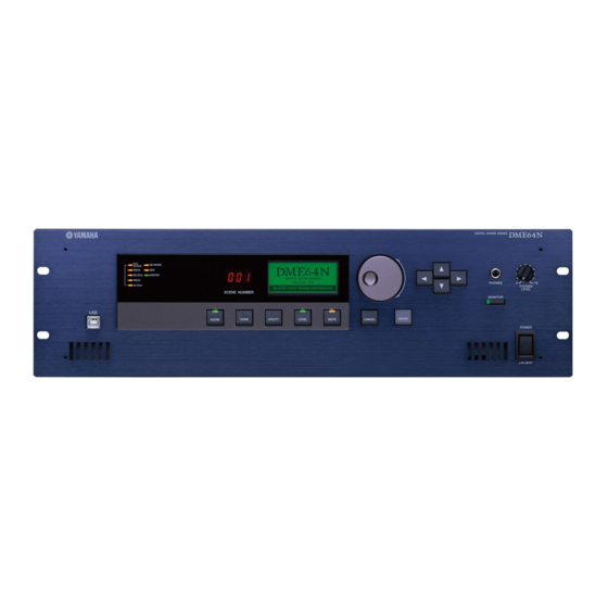
Front Panel The Controls and Connectors Front Panel DME64N DME24N 1 [USB] Connector A computer can be connected here when it is necessary to program or control the device. When a USB connection is to be used, the USB-MIDI driver must be installed on the computer. -
Page 15: Level] Button
5 [MIDI] Indicator Lights while data communication is occurring via the [MIDI] connector. Received data causes the indicator to light green, while transmitted data causes the indicator to light orange. The indicator will light green when reception and transmission occur simultaneously. If a problem occurs the indicator will light red. -
Page 16: Rear Panel
Rear Panel Rear Panel DME64N DME24N 1 [AC IN] Connector This is the device’s three-pronged AC power connector. Connect to the AC mains using the supplied AC power cord. See “Setup” on page 18 for details. NOT E Use the supplied AC cord clamp to prevent accidental disconnection of the AC power. - Page 17 Yamaha AD824 or AD8HR remote head amplifier or an RS-232C/RS-422 compatible controller such as those from AMX or Crestron. You can also connect a Yamaha PM5D or DM2000 and control the internal head amps of DME24N. Refer to page 28 for connection details.
-
Page 18: Setup
Use only the AC power cord supplied with the DME64N/24N. If the supplied cord is lost or damaged and needs to be replaced, contact your Yamaha dealer. The use of an inappropriate replacement can pose a fire and shock hazard! - Page 19 Install the DME Designer software and necessary drivers on the computer to be used for device group control. See the “DME Setup Manual” (PDF file) for details. Connect devices. • Network connection Ethernet connection (page 23) USB connection (page 22) •...
-
Page 20: I/O Card Installation
KK, KL, KM, KN, KO, KP, KX, KY are the third and fourth digits of the serial number. A fee is charged for the hardware upgrade. For details, contact Yamaha customer support using the contact information located at the end of the “DME64N/24N Owner’s Manual.”... -
Page 21: I/O Card Installation Procedure
I/O Card Installation Procedure Make sure that the DME64N/24N power is OFF. If the power is on, turn it off. Loosen the two card slot screws and remove the slot cover, as shown in the diagram. N OT E The slot cover and screws will need to be re-attached if the I/O card is later removed from the slot, so keep them in a safe place. Slide the I/O card into the slots in the guide rails, as shown in the diagram, and push the card into the slot. -
Page 22: Connecting To A Computer
USB Connection Connecting to a Computer USB Connection N OT E the “DME Setup Manual” (PDF file) • Refer to • Make sure that the USB-MIDI Driver’s THRU setting is “OFF.” USB connections can be used in the following two ways: (1) Control the DME64N/24N from DME Designer. -
Page 23: Ethernet Connection ([Network] Connector)
Ethernet Connection ([NETWORK] Connector) To control the DME64N/24N from the computer via Ethernet, use an Ethernet cable to connect the [NET- WORK] connector on the rear panel of the DME64N/24N to the computer, then install DME-N Network Driver. N OT E the “DME Setup Manual”... - Page 24 Use a STP (Shielded Twisted Pair) cable to prevent electromagnetic interference. • If you are using multiple DME series units, set Link Mode on each unit to the same setting. Yamaha recommends that you select 100Base-TX for the Link Mode setting.
- Page 25 Connecting multiple device groups Device Group 1 Group Master DME Satellite (IP address: 192.168.0.2) Ethernet Cable Switching Hub Ethernet Straight Cable Ethernet Cable CANCEL CANCEL SCENE SCENE HOME HOME UTILITY UTILITY LEVEL LEVEL MUTE MUTE DME64N/24N (IP address: 192.168.0.100) (Master ID: 2) INPUT PEAK PEAK...
-
Page 26: Audio I/O Connection
Utility display HA page described on page 54 of this manual, or via the DME Designer application. Euroblock Connection Please be sure to use the supplied Euroblock plugs. If you lose them, contact your nearest Yamaha dealer. • To prepare the cable for attachment to a Euroblock connector, strip the wire as shown in the illustration, and use stranded wire to make connections. -
Page 27: I/O Slots
Securely tighten terminal screws. Pull the cables (not too strongly) to confirm that they are securely connected. Plug the Euroblock plug into the panel connector. I/O Slots The DME64N has four I/O card slots, and the DME24N has one I/O card slot. The number of audio input channels available on the DME64N/24N can be increased by plugging the appropriate mini-YGDAI I/O card(s) into the available card slot(s). -
Page 28: Connecting To An External Device
Connecting to an External Device Remote Connection ([REMOTE] Connector) The [REMOTE] connector of the DME64N/24N can be connected to remotely-controllable Yamaha AD8HR or AD824 head amplifiers (pre-amps), digital mixers, or RS-232C compatible controllers (such as those from AMX or Crestron). The [REMOTE] connector also transmits and receives MIDI messages. -
Page 29: Controlling A Dme24N's Internal Head Amps From A Digital Mixer
Doing so can damage the unit. N OT E Refer to “DME Remote Control Protocol Specifications” on the Yamaha web site for more information on communication protocols used to control the DME64N/24N from an external device (such as those from AMX or Crestron). -
Page 30: Midi Connection ([Midi] Connectors)
MIDI Connection ([MIDI] Connectors) MIDI Connection ([MIDI] Connectors) In this case connection is made to the rear-panel [MIDI] connectors. MIDI commands are sent to the DME64N/24N from a MIDI device. N OT E Refer to “MIDI Page” on page 51 for MIDI setup details. N OT E The DME Designer can be used to set up the system so that scene recall operations and user parameter control can be carried out from connected MIDI devices. -
Page 31: Cascade Connection ([Cascade] Connectors) (Dme64N Only)
For information on the PM5D DME CONTROL function refer to the PM5D/PM5D-RH Owner’s Manual or to the “Cascade Setup Guide” available at the Yamaha website. http://www.yamahaproaudio.com/ Cascade Connection ([Cascade] Connectors) (DME64N only) -
Page 32: Word Clock Connection
WORD CLOCK Connection ([WORD CLOCK] Connectors) WORD CLOCK Connection ([WORD CLOCK] Connectors) Word clock signals are transferred to and from external devices via the [WORD CLOCK IN] and [WORD CLOCK OUT] connectors. The [WORD CLOCK OUT] connector can be used to supply the DME64N/ 24N word clock to external equipment. -
Page 33: Gpi Connection ([Gpi] Connectors)
GPI Connection ([GPI] Connectors) GPI (General Purpose Interface) device (GPI controller, etc.) can be connected to the rear-panel [GPI] connectors. Using GPI a variety of control signals can be transferred between the DME64N/24N and external controllers or other devices. The optional CP4SW, CP4SF, and CP1SF control panels are also connected via GPI. -
Page 34: Panel Operation And Displays
Basic Operation Panel Operation and Displays Basic Operation By pressing the panel keys it is possible to select the DME64N/24N Main display, Utility display, and Parameter Edit displays that allow individual settings to be edited and changed. refer to the pages listed below for more detailed information about each display. -
Page 35: Main Display
Main Display The Main display will appear in a few seconds after the power is turned on. The Main display shows information about the current scene. NOT E Nothing will appear on the display if no scene data is stored in the DME64N/24N scene memory (this is the case when the unit is initially shipped, for example). -
Page 36: Parameter Edit Displays
Parameter Edit Displays Panel Lock The panel controls can be “locked” to prevent accidental mis-operation. To activate the panel lock function simultaneously press and hold the [HOME] and [ENTER] keys for longer than 2 seconds. The panel lock icon will appear on the Main display when the panel is locked. - Page 37 Some Parameter Edit displays have just one numeric parameter, while other may have two or more. Parameter Edit Display with One Numeric Parameter Numeric values can be changed by rotating the dial. Dial rotation produces an immediate, corresponding change in the selected value. Press the [ENTER] key to close the Parameter Edit display after the value(s) have been edited as required.
-
Page 38: Editing User Defined Button
Parameter Edit Displays List Parameters List parameters allow you to make one selection from a list of possibilities. Rotate the dial to scroll up or down the list. In some cases the centermost item on the display will be always highlighted as the list is scrolled, and in others the same item will remain highlight as the list is scrolled up or down. -
Page 39: Mute Switching
Mute Switching Turns the DME64N/24N output mute function ON or OFF. Press the [MUTE] key. The Mute Parameter Edit display will appear. Select Mute ON or OFF. The mute function is turned on or off as described in “ON/OFF Parameters” on page 38. NOT E To access this function from the ICP1 control panel, hold the [F6] key for longer than 2 seconds. -
Page 40: Scene Store
Parameter Edit Displays NOT E Scenes can also be changed from a computer or GPI/MIDI controller connected to the device. The DME Designer application is used to make scene changes from a computer. If a GPI/MIDI controller is to be used for changes it must be initially set up for scene change control by using the DME Designer. -
Page 41: Spectrum Display
Select the desired monitor point from the list. The audio signal from the selected monitoring point will be output via the PHONES jack and the [MONITOR] indicator lights up. NOT E Press the [CANCEL] key to move back to the previous edit display. -
Page 42: Level Meter Display
Level Meter Display 4 L/R Select Indicates when the spectrum display is for the left or right channel. The same spectrum display will be shown for the L and R channels of all monitor points other than user- defined points specified via the DME Designer application. -
Page 43: Initializing The Dme64N/Dme24N
Begin with the power turned off. Turn the power on while holding the [SCENE] and [ENTER] buttons, and continue to hold those buttons until the Yamaha logo appears. The initialization screen will appear, allowing you to choose one of the following three options. -
Page 44: Utility Displays
Utility Displays Utility Displays Most basic DME64N/24N functions can be accessed via the Utility Display. Items accessible via the Utility display Page Item Info Current status and settings for the devices basic parameters. Label Name display. Version The device’s current version number. Date Current status and setup for the internal calendar/clock. - Page 45 Page Item CASCAD Displays current status for the [CASCADE] connectors. (DME64N Head Margin Displays current status for the head margin of the audio signal handled via the [CASCADE] connectors. only) Unit No. Displays how many devices the unit is from the beginning of the cascade chain. Mixer I/O Displays current status for the channels to be used for audio signals cascaded to a mixer.
-
Page 46: Utility Display Operation
Utility Displays Utility Display Operation The general procedure for operating the Utility displays is outlined below. Press the [UTILITY] key for longer than 2 seconds from the Main display to go to the Utility display. Press the [UTILITY] key as many times as necessary until the desired parameter page appears. -
Page 47: Network Settings (Net) Page
Network Settings (Net) Page Shows the Ethernet network address and other parameters. 1 Master/Slave Indicates whether or not the device is functioning as the device group master: “Master” or “Slave.” Master: the device is the device group master. Slave: the device is a device group slave. Edit using the “List Parameters”... -
Page 48: Lcd Backlight
If you forget your password the unit cannot be operated! If you forget your password contact the system administrator. If the password become unrecoverable for some reason and you need to unlock the system, please contact your Yamaha representative. 2 Panel Lock Boot Determines whether or not panel lock will be on when power to the device is turned on. -
Page 49: Miscellaneous Setup (Misc) Page
Miscellaneous Setup (Misc) Page This page includes parameters not available in any other page. NOT E The Remote setting (2) will not appear on the ICP1 control panel display. 1 Scene Store Determines whether or not scene store operations are allowed. -
Page 50: Word Clock Setup (Wclk) Page
“DME Remote Control Protocol Specifications” document. Information about the “DME Remote Control Protocol Specifications” document can be found at the Yamaha Pro Audio website (http:// www.yamahaproaudio.com/). NOT E This item cannot be set if Internal HA Ctrl is set to Remote. -
Page 51: Slot Information (Slot) Page
Slot Information (Slot) Page Displays the name of the card installed in an I/O card slot. Some cards can also be reset via this page. NOT E This page will not appear on the ICP1 display. 1 Card Name The name of the installed card appears here. 2 Reset Resets the installed card. -
Page 52: Program Change
Utility Displays NOT E “DAW” stands for “Digital Audio Workstation.” ProTools, Logic, and Cubase are DAW applications, and this parameter provides direct compatibility with a number of physical controls surfaces that are available for use with these DAW software packages. The following parameters are available when the DAW parameter is set to OFF. -
Page 53: Gpi Setup (Gpi) Page
2. Setting and parameter name display function Displays the settings and parameter names on the DAW controller’s LCD screen. There are two display methods: over-all display and detail display. Overall Display: The overall display shows the assigned parameter names and settings, organized by DAW channels. Detail Display: In the detail display, you select the parameter you want to display. -
Page 54: Head Amplifier Setup (Ha) Page
Utility Displays Head Amplifier Setup (HA) Page Provides access to the head amplifier settings. Refer to “REMOTE Connection” on page 28 for head amplifier control signal connection. NOT E This page will not appear on the ICP1 display. NOT E Some scenes include head amplifier settings. -
Page 55: Cascade Setup (Cascad) Page
4 Gain Individually sets the gain of each head amplifier channel. Edit using the “Numeric Parameters” editing procedure described on page 36. NOT E The gain of the DME24N internal head amplifiers can be adjusted from +10 dB to –60 dB in 1-dB increments. The internal circuitry switches at about the –45-dB point, and the signal is automatically muted at that point to prevent noise. -
Page 56: Check Page
Utility Displays 3 Mixer I/O Displays whether the cascade signal is bus shared or not. ■ : A DME64N connected directly to the mixer is connected to a second DME64N on this unidirectional channel. Input on the same channel from other DME64N units will be independent. -
Page 57: References
References Options The ICP1, CP4SW, CP1SF, and CP4SF controllers are available as options for remote external control of the DME series. The ICP1 connects via Ethernet, while the CP4SW, CP1SF, and CP4SF connect via the GPI interface. For more information on installing your Control Panel and connecting it to a DME series unit, refer to the owner’s manual that came with the Control Panel. -
Page 58: Error Messages
This does not affect the operation of the unit. However, if you continue using the unit, the settings may be lost and reset to the default values. Contact a Yamaha dealer for battery replacement at your earliest convenience. If you turn off the power to the unit, the current settings will be lost and reset to the default values. - Page 59 This could be due to a hardware malfunction. Refer this problem to a contact a Yamaha dealer. Set an appropriate network IP address. Check the devices connected to the network. If there are too many devices connected, reduce the number of devices.
- Page 60 Error Messages Message SLOT4 Sync Err The DME64N clock is not synchronized with the clock of the card installed in I/O slot 4. Synchronizing Data is being received from the computer. Do NOT turn Do not turn off power off while the unit displays this message. Updating Data is being received from the computer.
-
Page 61: Troubleshooting
LCD won’t light. • Is the POWER switch turned on? • If neither of the above is the problem, contact your Yamaha service center or representative. Cannot exchange data between the • Are the network cables connected correctly? DME64N/24N and the DME Designer. -
Page 62: Specifications
Specifications Specifications Specifications and descriptions in this owner’s manual are for information purposes only. Yamaha Corp. reserves the right to change or modify products or specifications at any time without prior notice. Since specifications, equipment or options may not be the same in every locale, please check with your Yamaha dealer. -
Page 63: Input/Output Characteristics
Input/Output Characteristics DME24N ANALOG INPUT CHARACTERISTICS Input Level Actual For Use Terminals Gain Load With Nominal Impedance Nominal CH INPUT -60dB 3kΩ 50 – 600Ω -60dBu 1 – 8 Mics & (0.775mV) 600Ω +10dB +10dBu Lines (2.451V) • 0dBu = 0.775 Vrms •... -
Page 64: Control I/O
Control I/O Control I/O Terminals REMOTE MIDI WORDCLOCK Ethernet DME64N: 16-GPI inputs and 16-GPI outputs DME24N: 8-GPI inputs and 8-GPI outputs Outputs: Imax/pin = 16mA Outputs: VH = 2.5V(min.), VL = 0.6V(max.) DME64N/DME24N Owner’s Manual Format Level RS232C RS422 IN/OUT/THRU IN/OUT TTL/75Ω... -
Page 65: Connector Pin Assign
Connector Pin Assign [CASCADE IN/OUT] Connectors (DME64N only) CASCADE IN Signal INPUT 1-2 (+) INPUT 3-4 (+) INPUT 5-6 (+) INPUT 7-8 (+) INPUT 9-10 (+) INPUT 11-12 (+) INPUT 13-14 (+) INPUT 15-16 (+) DTR IN (+) RTS OUT (+) WORD CLOCK IN (+) WORD CLOCK OUT (+) CONTROL IN (+) - Page 66 Connector Pin Assign [NETWORK] Connector (100Base-TX Ethernet, RJ-45) Connection Unused Unused Unused Unused Straight/Cross Cable Wiring Details Straight Cables Pins 1 —— 1 2 —— 2 3 —— 3 4 —— 4 5 —— 5 6 —— 6 7 —— 7 8 ——...
-
Page 67: Dimensions
Dimensions DME64N 4-M3 DME24N 4-M3 DME64N/DME24N Owner’s Manual Dimensions Unit: mm... -
Page 68: Midi Data Format
MIDI Data Format MIDI Data Format 1. DME64N/24N MIDI Functions 1.1 Scene Change Scene recall occurs according to the “MIDI Program Change Table” assignments when appropriate MIDI Bank Select MSB/LSB and Program Change messages are received by the DME64N/24N. Corresponding MIDI Bank Select MSB/LSB and Program Change messages are also transmitted by the DME64N/24N when a scene recall operation is carried out via the panel controls, as specified by the “MIDI Program Change Table”... - Page 69 3. MIDI Setup Specifies basic MIDI operation. 3.1 Host Select Selects the input/output port to be used for MIDI communication. 3.2 DAW Controller Specifies the DAW controller type when a DAW control surface is to be used to control the DME64N/24N. When Type 1/ 2 is selected, Host Select is automatically set to MIDI.
- Page 70 MIDI Data Format 4.1 Program Change (Cnh) Receive When the “Program Change Rx Switch” is on, Program Change messages are received on the MIDI channel specified by the “MIDI Rx Channel” parameter. If the “Program Change Omni Switch” is also on, however, Program Change messages will be received on all MIDI channels regardless of the “MIDI Rx Channel”...
- Page 71 0 0 1 1 1 1 1 1 1 1 1 1 1 1 1 1 1 1 1 1 1 1 1 1 1 0 0 0 0 0 1 1 0 0 0 data 0 = 1Fh data 1 = 7Fh System Exclusive Message Manufacturer's ID No.(YAMAHA) Rx/Tx Channel (0-15) Digital Mixer Device Code (DME)
- Page 72 MIDI Data Format YAMAHA [Digital Mixing Engine] Model DME64N/24N MIDI Implementation Chart Function... Basic Default Channel Changed Default Mode Messages Altered Note Number : True voice Velocity Note ON Note OFF After Key's Touch Ch's Pitch Bend 0,32 1-31,33-95,102-119 Control...
-
Page 73: Glossary
A type of connector used for high-frequency connections using thin-core coaxial cable. An internal spring ensures a solid connection. A means of connecting Yamaha digital audio equipment to allow transfer of audio, control, and word clock signals. Yamaha cascade connections employ half-pitch 68-pin D-Sub connectors. - Page 74 Glossary Terms Phantom Power Preset Parameter RJ-45 Router RS-232C RS-422 Sampling Frequency Scene STP (Shielded Twisted Pair) Cable Switching Hub TDIF (Tascam Digital Interface Format) USB (Universal Serial Bus) UTP (Unshielded Twisted pair) Cable Word Clock DME64N/DME24N Owner’s Manual Explanations A power delivery system that allows power to be delivered to devices along with audio signals via standard balanced audio cables.
-
Page 75: Head Amplifier Setup (Ha)
Index +48V ... 55 [E ] [ ▲ ] [ ▼ ] [F ] Buttons ... 15 100Base-TX (Glossary) ... 73 10Base-T (Glossary) ... 73 [96kHz] [88.2kHz] [48kHz] [44.1kHz] Indicator ... 14 [AC IN] Connector ... 16 ADAT (Alesis Digital Audio Tape) (Glossary) ... 73 AES/EBU (Audio Engineering Society/European Broadcasting Union) (Glossary) ... - Page 76 [MIDI] Indicator ... 15 MIDI Page ... 51 MIDI Setup (MIDI) Page ... 51 MIN ... 53 Mini YGDAI (Yamaha General Digital Audio Interface) card (Glossary) ... 73 Misc Page ... 49 Miscellaneous Setup (Misc) Page ... 49 Mixer I/O ... 56 [MONITOR] Button ...
- Page 77 SLOT1~4 ... 50 SP (Double Speed) ... 51 specifications ... 62 Spectrum display ... 41 status message ... 58 STP (Shielded Twisted Pair) Cable (Glossary) ... 74 Switching Hub (Glossary) ... 74 TDIF (Tascam Digital Interface Format) (Glossary) ... 74 troubleshooting ...
- Page 78 MEMO DME64N/DME24N Owner’s Manual...
- Page 79 For details of products, please contact your nearest Yamaha representative or the authorized distributor listed below. Pour plus de détails sur les produits, veuillez-vous adresser à Yamaha ou au distributeur le plus proche de vous figurant dans la liste suivante.
- Page 80 Yamaha Pro Audio global web site: http://www.yamahaproaudio.com/ Yamaha Manual Library http://www.yamaha.co.jp/manual/ U.R.G., Pro Audio & Digital Musical Instrument Division, Yamaha Corporation © 2004 Yamaha Corporation WK83840 906MWCPx.x-02E0 This document is printed on chlorine free (ECF) paper with soy ink. Printed in Japan...